10
STEMkW Special ed 01/08 EOLO Mini kW Special
Technical DocumentationTechnical Documentation
8
8
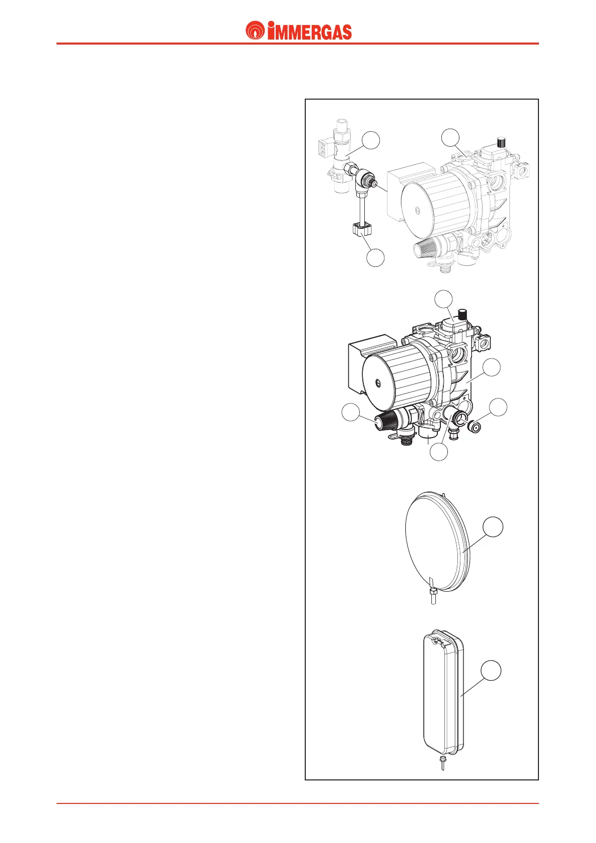
EOLO Mini 24 kW Special
EOLO Mini 28 kW Special
Safety devices and checks.
Automatic system by-pass (3).
is device guarantees the circulation of water in the central
heating circuit even when it would be prevented by the high
resistance of the system.
It works between the central heating ow and return, inserted
inside the by-pass tting (4) that connects the pump unit (2)
to the 3-way unit.
System lling unit (7).
is is a valve positioned between the boiler circuit and the
domestic cold water inlet and makes it possible to pressurise
the heating system.
is unit is connected to the d.h.w. ow switch (6) by means
of a threaded tting and to the pump unit (2) by means of
an O ring.
Automatic air vent (1).
It automatically expels gaseous substances from the boiler
circuit.
It is mounted on the circulator ow, directly on the pump
unit (2).
3-bar safety valve (5).
is valve prevents the safety pressure being exceeded in the
primary circuit (3 bar).
It tted on the front of the pump unit (2) and xed on the
outside by means of a fork.
When this valve triggers, water exits from the boiler return
pipe.
Expansion vessel (8).
It compensates for variations in volume as a result of heating
the water which also limits pressure variations.
It has a 6-litre capacity (4.5 useful litres) for the 24 model and
7.5 litres (4.5 useful litres) for the 28 model and a preload
pressure of 1.0 bar.
In the 24 model it is rectangular in shape and located on the
right-hand side of the boiler, by the side of the sealed cham-
ber while, in the 28 model it is circular in shape and located
at the rear of the boiler, behind the sealed chamber; in both
models a copper pipe connects the expansion vessel to the
pump unit (2).