20
STEMkW Special ed 01/08 EOLO Mini kW Special
Technical DocumentationTechnical Documentation
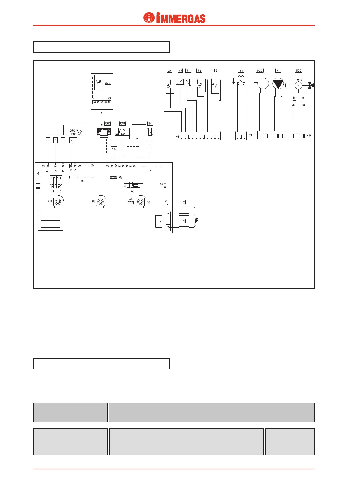
e electrical circuit of the EOLO Mini 24-28 kW Special
boiler is controlled 100% by a P.C.B. which controls boiler
functions.
Some of the control and safety devices work at mains voltage
(230 V AC) while others at low voltage.
Electrical circuit.
Legend:
A5 - CAR interface board
B1 - Flow probe
B4 - External probe (optional)
CAR - Comando Amico Remoto remote control
(optional)
CRD- Digital Remote Control (optional)
CZ - Zone control unit (optional)
E1 - Ignition electrodes
E2 - Detection electrode
E4 - Safety thermostat
F1 - Neutral fuse
F2 - Line fuse
M1 - Boiler pump
M20 - Fan
M30 - 3-way valve
R5 - D.h.w. temperature trimmer
R6 - Central heating temperature trimmer
R10 - Main switch
S4 - D.h.w. ow switch
S6 - Flue pressure switch
S8 - Gas type selector
S20 - Room thermostat (optional)
T2 - Ignition transformer
X40 - Room thermostat jumper
Y1 - Gas valve
Y2 - Gas valve modulator
;0/&
$0/530-
6/*5
1SJNBSZ
4FDPOEBSZ
(-1
/"5("4
1PXFS
7BD
)[
"VYJMJBSZ
PVUQVU
230 V AC circuit.
Safety and control devices.
Detects whether the burner is it (enveloped by ame).
Connected to the integrated P.C.B.
Detection electrode
(E2)
Disconnects power supply to the circuit when the input current
exceeds 3.15 A.
Assembled on the integrated P.C.B.
Line fuse (F1)
Neutral fuse (F2)
Fuse
3.15 AF 250 V