15
STEMkW Special ed 01/08 EOLO Mini kW Special
Technical Documentation
Technical Documentation
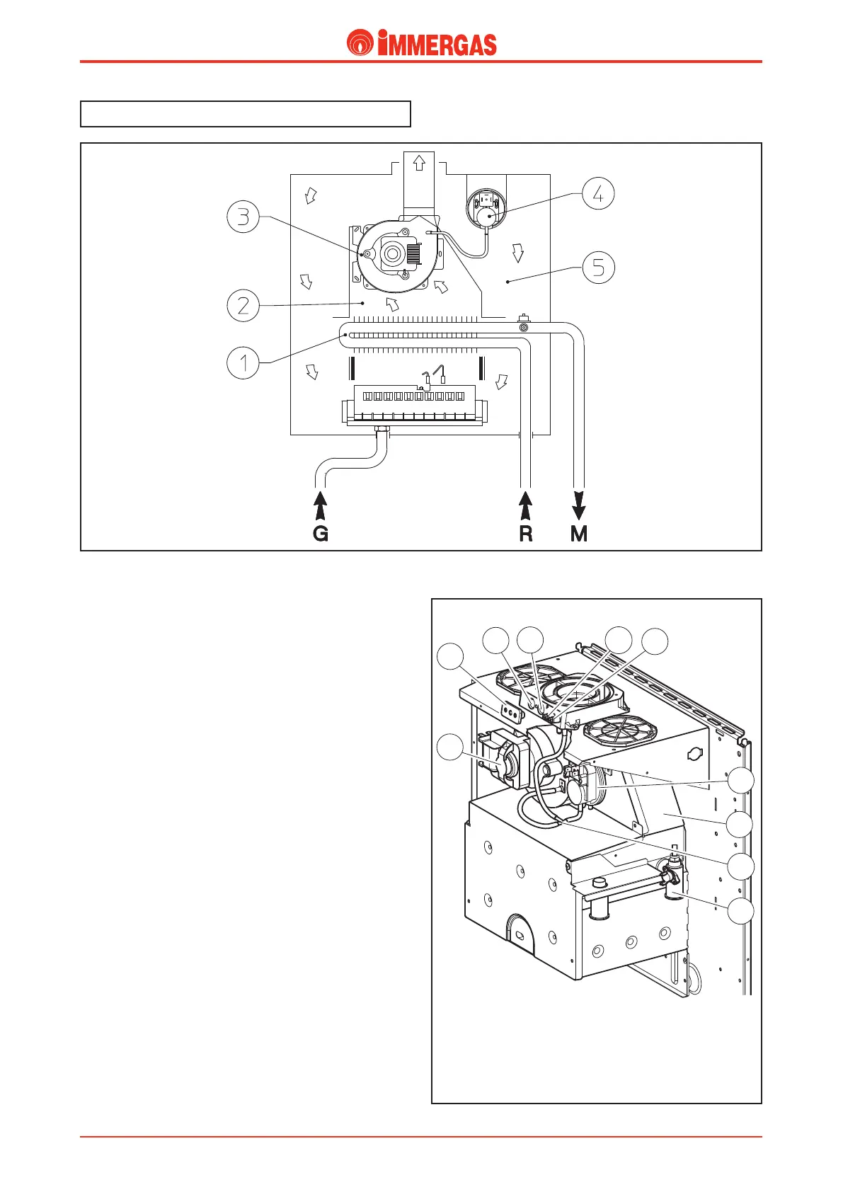
Flue circuit.
Operation.
e products of combustion, after hitting the water-gas exchan-
ger (1), are conveyed to a hood (2) on top of which the fumes
extractor (3) is tted (fan).
Fan operation guarantees the forced expulsion of the fumes
and, at the same time, creates a vacuum in the sealed chamber
(5) so the combustion air can be aspirated from outside.
Correct fume extraction is controlled by a dierential ue
pressure switch (4); when it triggers it either enables or prevents
burner ignition.
Air/fumes testing holes (7-8).
ere are two holes at the top on the outside of the sealed
chamber which can be accessed from the front; they are used
to sample combustion air (7) and fumes (8).
e two holes are closed by the one plastic cap (6).
Flue pressure switch signal pressure points (9-
10).
ere are two pressure points with screw closing at the top on
the outside of the sealed chamber. ey measure the signal at
the ends of the ue pressure switch (4).
e negative pressure point (9) is connected to a Y-shaped
pipe (11) which, in turn, is connected to the negative pressure
point of the ue pressure switch (4) and to the pressure point
on the fan.
e positive pressure point (10) is connected directly to the
inside of the sealed chamber.