10
1-9
1-10
1-8
1-11
1-12
INSTALLERUSER
MAINTENANCE TECHNICIAN
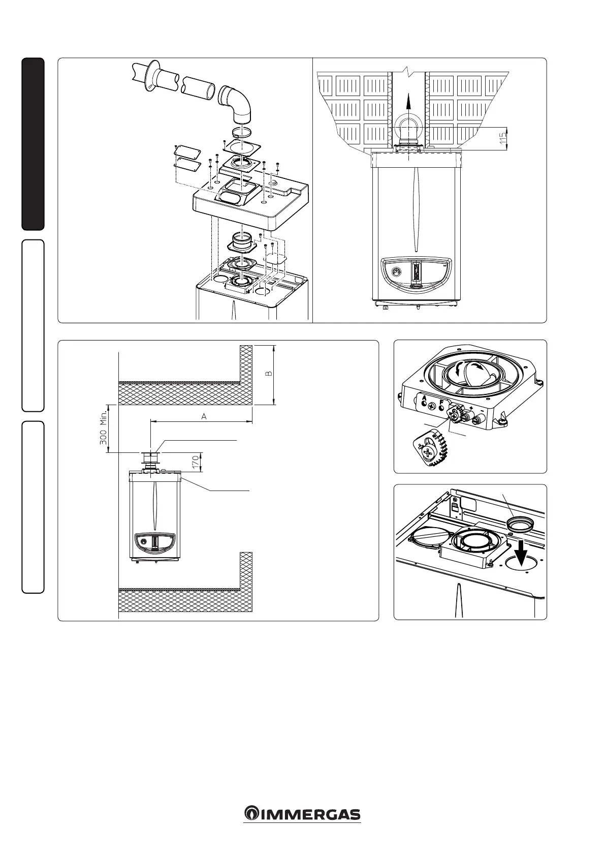
VERTICAL TERMINAL KIT
FOR DIRECT DRAINING
INTAKE
COVER KIT
DIAPHRAGM
Flue gas separator adjustment. For correct fun-
ctioning of the boiler it is necessary to regulate
the ue gas shutter positioned on the air/ue gas
sample points (Fig. 1-11).
Adjustment is carried out by loosening the
front retainer screw and moving the indicator
to the correct position, aligning its value to the
horizontal reference. Once adjustment has been
performed, tighten the screw to x the separator.
Appropriate adjustment takes place on the basis
of the type of pipe and its extension: this calcula-
tion can be carried out using the relevant tables.
Intake diaphragm installation. For correct boi-
ler functioning with Ø80 separator kits and drain
measuring > 1 m a diaphragm must be installed
on the sealed chamber intake hole and before
the intake pipe (Fig. 1-12). e choice of suitable
diaphragm takes place on the basis of the type of
pipe and its maximum extension: this calculation
can be carried out using the following tables:
N.B.: the diaphragms are supplied together with
the boiler.
e cover kit includes:
N° 1 Heat moulded cover
N° 1 Gasket clamping plate
N° 1 Gasket
N° 1 Gasket clamp
N° 1 N°1 Intake hole covering
plate
e terminal kit includes:
N° 1 Gasket
N° 1 Exhaust ange Ø80
N° 1 Bend 90° Ø80
N° 1 Exhaust pipe Ø80
N° 1 Wall sealing plate