11
STMiN3E ed 09/11 MINI NIKE 3 E
Technical Documentation
Technical Documentation
Flow
heat exchanger
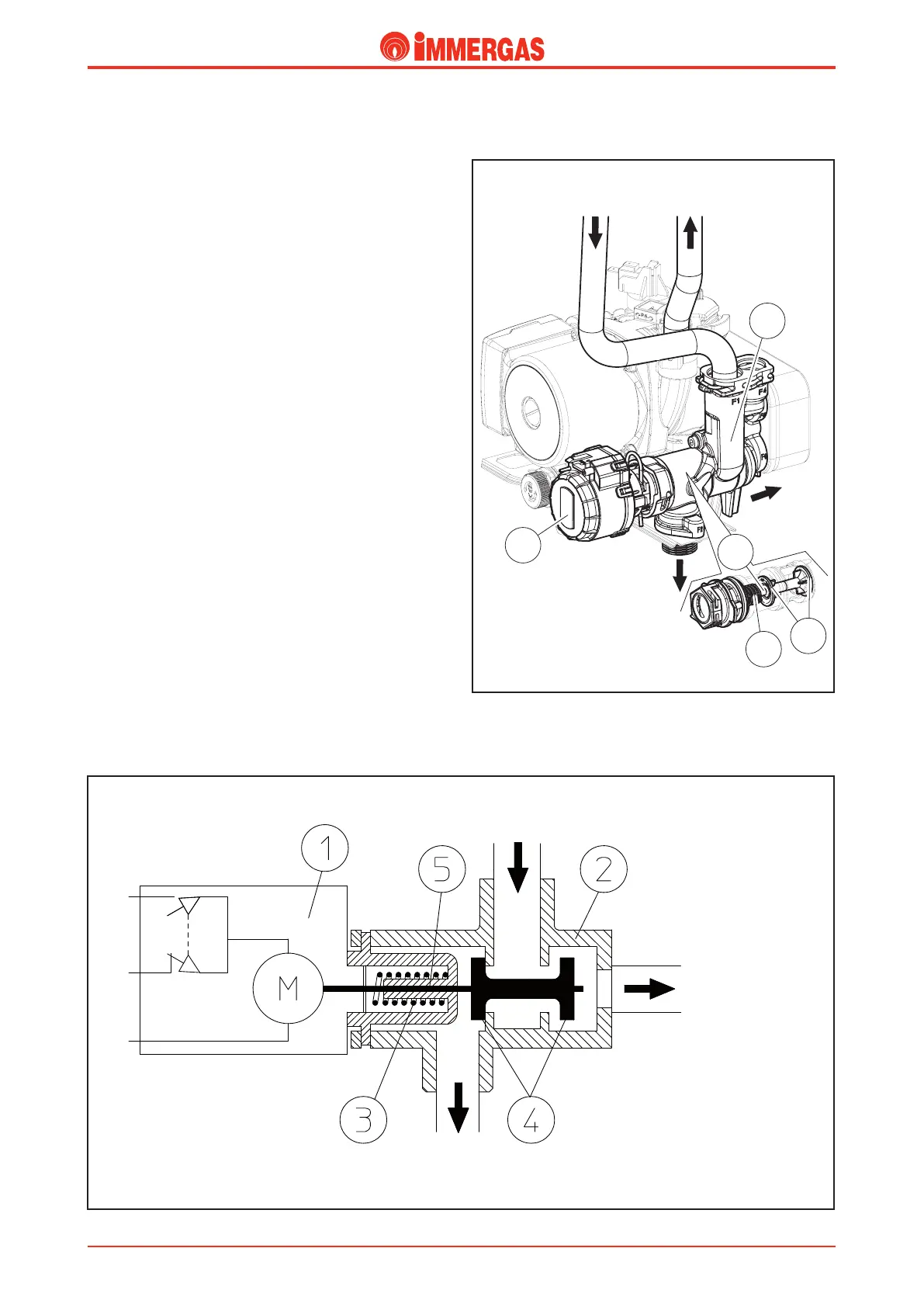
Motorised 3-way valve
is is composed of an electric motor (1) connected to the
three-way group (2) with a clip.
Based on the request (DHW or CH), the three-way clip allows
boiler water to enter the heating system or in the DHW (plate)
heat exchanger.
is depends on the position of the shutter (4) which closes
the passage to the system and at the same time opens the
passage to the DHW heat exchanger (DHW position), or vice
versa (CH position).
e motor (1) is operated by the P.C.B. and moves the shutter
(4) in both positions.
e hydraulic part is made of a group built with composite
material (2).
Operation during the heating phase
e counter spring (3) for the shutter (4) is not compressed
(heating position), keeping the passage towards the DHW
(plate) heat exchanger closed and the passage towards the
system ow open.
Both the spring (3) and the shutter (4) are situated inside the
body of the 3-way cartridge made from composite material (2).
Operation in domestic hot water phase
e hydraulic group is kept in the DHW phase position.
e electric motor (1) pushes the stem (5) that the shutter is
attached to (4), closing the passage towards the system, and at
the same time opening the passage towards the DHW (plate)
heat exchanger, compressing the counter spring (3) for the
shutter (4) (DHW position).
Both the spring (3) and the shutter (4) are situated inside the
body of the 3-way cartridge made from composite material (2).
Return
heat exchanger
1
2
5
4
3
Flow
heat exchanger
DHW
Flow
system
FLOW
HEAT EXCHANGER
FLOW
SYSTEM
FLOW
HEAT EXCHANGER
DHW