12
STMiN3E ed 09/11 MINI NIKE 3 E
Technical DocumentationTechnical Documentation
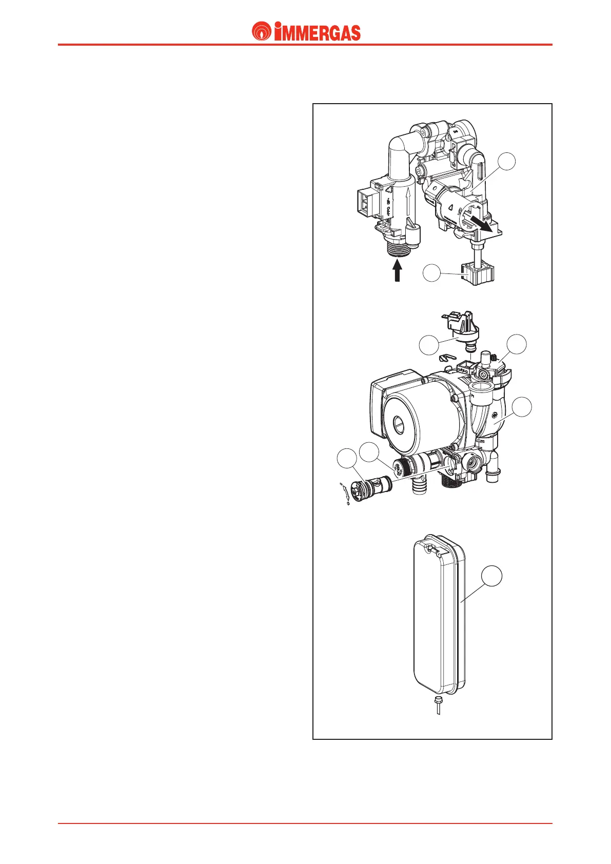
Safety devices and controls
Adjustable system by-pass (5)
is guarantees circulation in the CH circuit even when the
high resistance of the system does not allow it.
It operates between the ow and return of the CH circuit.
It is push-tted into the top of the pump group (3) and is
locked with a clip. It is accessible from the front of the pump
group itself and can be adjusted using a screwdriver.
System lling unit (7)
is is a pin valve positioned between the boiler circuit and
the domestic cold water inlet that enables the CH system to
be placed under pressure.
e valve is connected to a manifold (6) which is in turn
connected to the cold water input and the pump group with
a locking clip.
System pressure switch (1)
It detects the pressure inside the primary circuit.
Its seat is built into the pump group (3) and is coupled to a
micro switch that prevents the burner from operating when
the detected pressure is below 0.3 bar.
It prevents the primary heat exchanger from overheating.
Automatic air vent valve (2)
is allows the gaseous substances that may be present in the
boiler circuit to be automatically expelled.
It is mounted on the pump ow directly on the pump group
(3).
3 bar safety valve (4)
is prevents the primary circuit from exceeding the safety
pressure (3 bar).
It is push-tted into the front part of the pump group (3) and
is attached to the external side using a clip.
Its intervention causes water to leak from the boiler return.
Expansion vessel (8)
It compensates the variations in volume caused by heating the
water, thus limiting the pressure variations.
It has a capacity of 6 litres (eectively 4.5 litres) and a factory-
set pressure of 1.0 bar.
It has a rectangular shape and is positioned on the right side
of the boiler next to combustion chamber and is connected
to the pump unit by means of a copper pipe.
8
5
1
2
3
4
7
6