20
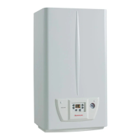
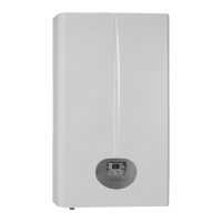
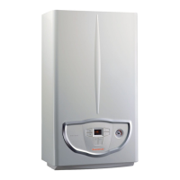
STMiN3E ed 09/11 MINI NIKE 3 E
Technical DocumentationTechnical Documentation
Gas adjustments
The minimum and maximum pressure adjustments are
performed by acting on the gas valve and must be carried
out respecting the values stated in the tables relative to each
generator for the corresponding type of gas (see technical data).
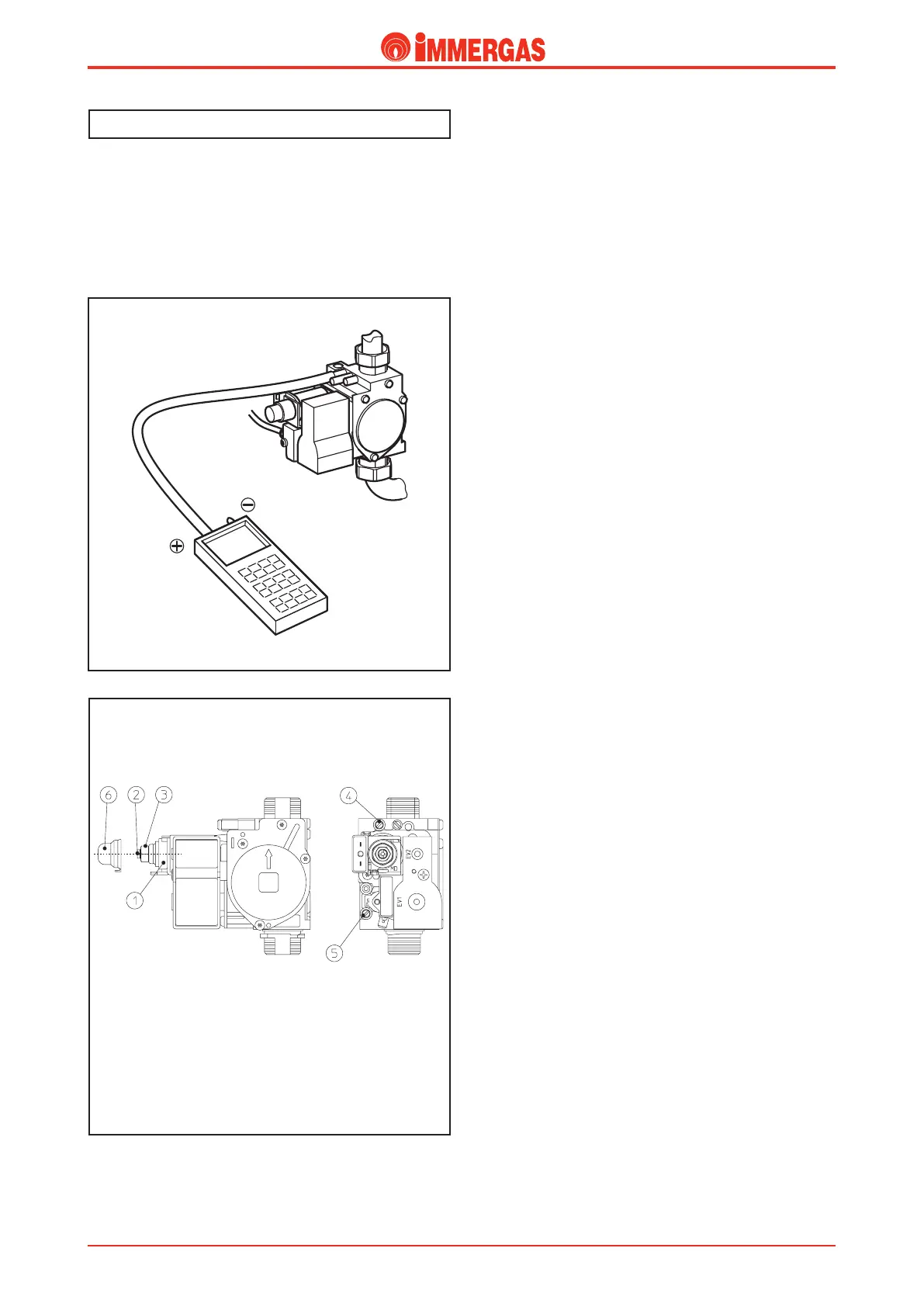
e measurements are taken using a dierential manometer,
whose pressure point is connected to the vas valve outlet (4)
(see gure).
Key:
1 - Coil
2 - Minimum power adjustment screws
3 - Maximum power adjustment nut
4 - Gas valve outlet pressure point
5 - Gas valve inlet pressure point
6 - Protection hood
SIT 845 Valve
SIT 845 Gas Valve
Maximum pressure adjustment
Draw DHW after having positioned the temperature dial on
maximum.
Act in a clockwise direction on the brass nut (3) to increase
the pressure to the burner and in a clockwise direction to
decrease it.
Minimum pressure adjustment
(to be carried out after adjusting the maximum pressure)
After disconnecting the power supply from the modulation
coil, turn the screw clockwise (2) to increase the pressure in
the burner and counter-clockwise to reduce it.
Gas transformation
e adaptation to the type of gas dierent to that for which
the boilers are prepared as per standard is performed using the
relevant kit (methane or LPG).
e transformation consists in replacing the nozzles of the
burner and selecting the parameter for the type of gas (G1)
on the boiler push button panel; then select (nG) for Methane
or (lG) for L.P.G.
e maximum and minimum DHW pressures are adjusted
on the gas valve in the manner described above.
e adjustments of the minimum and maximum outputs in
CH mode can be set using parameters (see integrated P.C.B.
functioning).
e ignition pressure for the burner can be adjusted and
set using the "Ignition Output" (G2) parameter with the
same value as "Minimum heating output" (see Operating the
integrated P.C.B.).