14
3-2
5
1
2
6
5
4
3
4
4
5
11
7
7
7
12
12
7
13
13
11
5
7
4
10
10
10
10
9
8
INSTALLATORUSER
MAINTENANCE TECHNICIAN
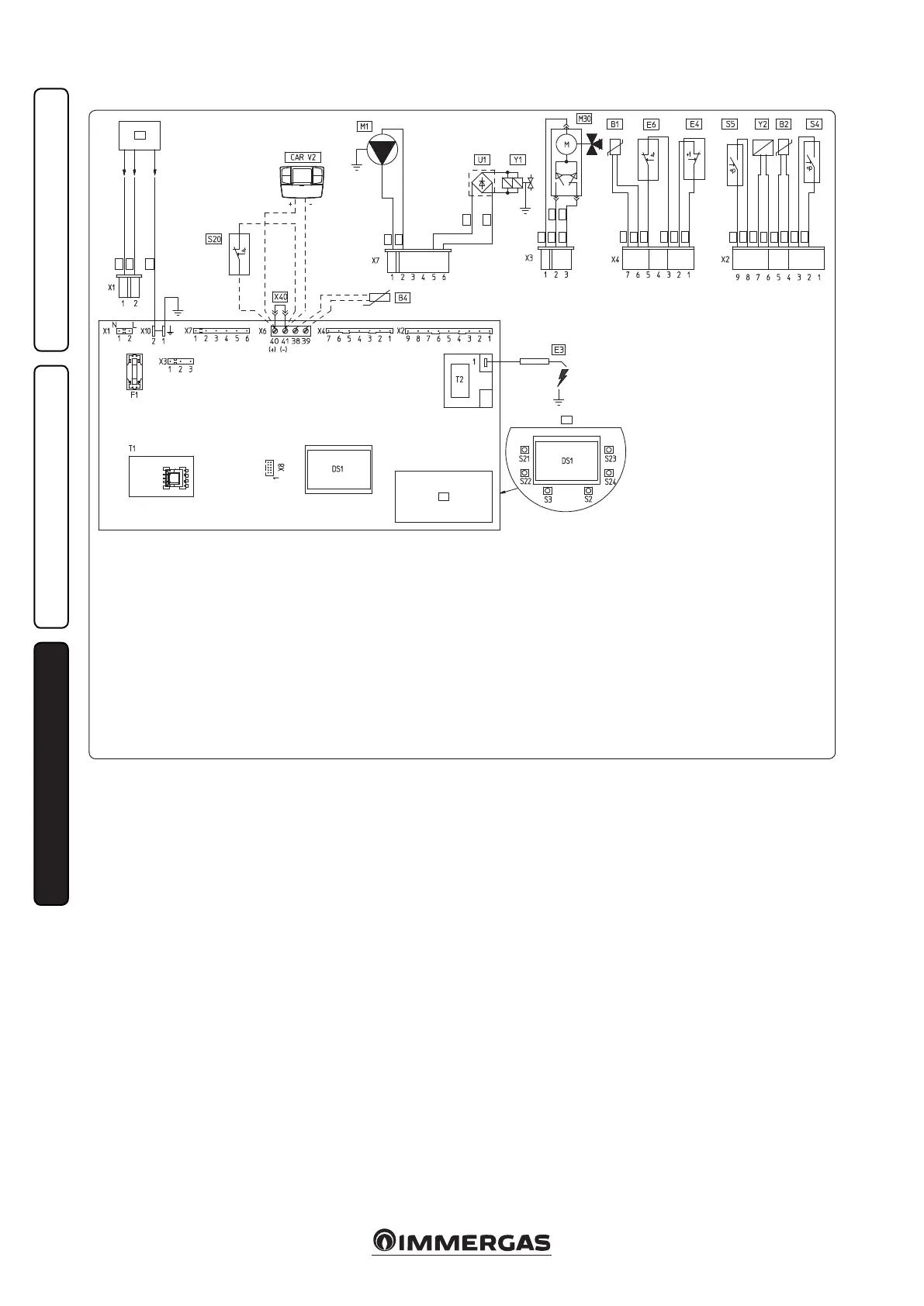
3.2 WIRING DIAGRAM.
Key:
B1 - Flow probe
B2 - Domestic hot water probe
B4 - External probe
CAR V2 - Comando Amico Remoto remote
control Version 2 (optional)
DS1 - Display
E3 - Ignition and detection electrodes
E4 - Safety thermostat
E6 - Flue safety thermostat
F1 - Phase fuse
M1 - Boiler pump
M30 - ree-way valve
S2 - Selector switch functioning
S3 - Reset block key
S4 - Domestic hot water ow switch
S5 - System pressure switch
S20 - Room thermostat (optional)
S21 - Domestic hot water temperature
increase key
S22 - Domestic hot water temperature
decrease key
S23 - Heating temperature increase key
S24 - Heating temperature reduce key
e boiler is designed for application of a room
thermostat (S20), an On/O room chronother-
mostat, a program timer or a Comando Amico
Remoto remote control
V2
(CAR
V2
). Connect
to clamps 40 - 41 eliminating the jumper X40,
paying attention not to invert the polarity if the
CAR
V2
is installed.
e connector X8 is used for the connection
of the Virgilio Palmtop in the microprocessor
soware updating operation.
3.3 TROUBLESHOOTING.
N.B.: maintenance interventions must be car-
ried out by an authorised rm (e.g. Technical
Assistance Service).
- Smell of gas. Caused by leakage from gas circuit
pipelines. Check sealing eciency of gas intake
circuit.
- Irregular combustion (red or yellow ame).
When the burner is dirty or the boiler lamellar
pack is blocked. Clean the burner or the boiler
lamellar pack.
- Frequent interventions of the over heat-
ing safety thermostat. It can depend on
the lack of water in the boiler, little water
circulation in the system or blocked pump.
Check on the manometer that the sys-
tem pressure is within established limits.
Check that the radiator valves are not closed
and also the functionality of the pump.
- e boiler produces condensate. is can be
caused by obstructions of the chimney or ues
with height or section not proportioned to the
boiler. It can also be determined by function-
ing at boiler temperatures that are excessively
low. In this case, make the boiler run at higher
temperatures.
- Frequent interventions of the ue safety ther-
mostat is can be caused by obstructions in
the ue gas circuit. Check the ue. e ue
may be obstructed or by height or section
not suitable for the boiler. Ventilation may be
insucient (see room ventilation point).
- Presence of air in the system. Check opening
of the hood of the special air vent valve (Fig.
1-7). Make sure the system pressure and expan-
sion vessel pre-charge values are within the set
limits; the pre-charge value for the expansion
vessel must be 1.0 bar, and system pressure
between 1 and 1.2 bar.
- Ignition block and Chimney block. (See par.
2.6 and 1.5 electric connection).
T1 - Low voltage feeder
T2 - Switch-on transformer
U1 - Rectier inside the gas valve
connector (Only available on
Honeywell gas valves)
X40 - Room thermostat jumper
Y1 - Gas valve
Y2 - Gas valve modulator
1 - User interface
2 - N.B.: e user interface is on
the welding side of the boiler
board
3 - 230 Vac 50Hz power supply
4 - Blue
5 - Brown
6 - Yellow/Green
7 - Black
8 - (DHW)
9 - (central heating)
10 - Grey
11 - White
12 - Red
13 - Green