7
1-6
A
B
C
D
INSTALLATORUSER
MAINTENANCE TECHNICIAN
1.11 SYSTEM FILLING.
Once the boiler is connected, ll the system via
the lling valve (Fig. 2-2). Filling is performed
at low speed to ensure release of air bubbles in
the water via the boiler and heating system vents.
e boiler has a built-in automatic venting valve
on the circulator. Open the radiator vent valves.
Close radiator vent valves only when water es-
capes from them.
Close the lling valve when the boiler manometer
indicates approx. 1.2 bar.
N.B.: during these operations start up the cir-
culation pump at intervals, acting on the main
switch positioned on the control panel. Vent the
circulation pump by loosening the front cap and
keeping the motor running.
Tighten the cap aer the operation.
1.12 GAS SYSTEM STARTUP.
To start up the system, make reference to the
Standard.
In particular, for new gas systems:
- open windows and doors;
- avoid presence of sparks or naked ames;
- bleed all air from pipelines;
- check that the internal system is properly sealed
according to specications.
1.13 BOILER START UP IGNITION.
For issue of the envisioned Declaration of Con-
formity, the following must be performed for
boiler start-up (the following operations must
only be performed by an authorised company
and only in the presence of sta):
- check that the internal system is properly sealed
according to specications
- make sure that the type of gas used corresponds
to boiler settings;
- check that there are external factors that may
cause the formation of fuel pockets;
- switch the boiler on and check correct ignition;
- make sure that the gas ow rate and relevant
pressure values comply with those given in the
manual (par. 3.18);
- check the correct ventilation of the rooms;
- check the existing draught during normal
functioning of the appliance, e.g. a draught
gauge positioned at the exit of the appliance
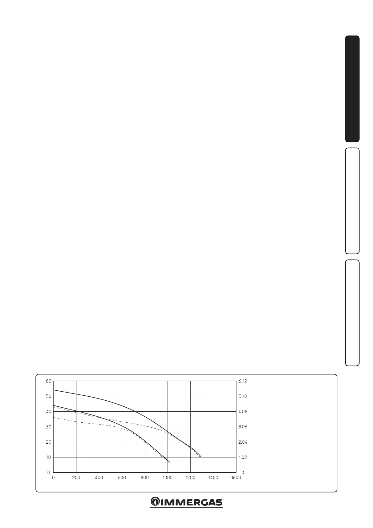
Total head available to the system.
Total head (m H
2
O)
Flow rate (l/h)
Head (kPa)
A = Head available to the
system at maximum speed
with by-pass excluded.
B = Head available to the
system at maximum speed
with by-pass inserted.
C = Head available to the
system at second speed with
by-pass excluded.
D = Head available to the
system at second speed with
by-pass inserted.
combustion products;
- check that there is no backow of combustion
products into the room, even during function-
ing of fans;
- ensure that the safety device is engaged in the
event of gas supply failure and check activation
time;
- check activation of the main switch located
upstream from the boiler.
e boiler must not be started up even if only
one of the checks should be negative.
1.14 CIRCULATION PUMP.
e Mini Nike 24 3 E series boilers are supplied
with a built-in circulation pump with 3-posi-
tion electric speed control. e boiler does not
operate correctly with the circulation pump on
rst speed. To ensure optimal boiler operation,
in the case of new systems (single pipe and
module) it is recommended to use the pump
at maximum speed. e pump is already tted
with a condenser.
Pump release. If, aer a prolonged period of
inactivity, the circulation pump is blocked,
unscrew the front cap and turn the motor sha
using a screwdriver. Take great care during this
operation to avoid damage to the motor.
By-pass regulation (part. 20 Fig. 1-7). If neces-
sary, the by-pass can be regulated according to
system requirements from a minimum (by-pass
excluded) to a maximum (by-pass inserted)
represented by the graphics (Fig. 1-6).
Make the regulation using a at head screw-
driver, turn clockwise and insert the by-pass,
anti-clockwise it is excluded.
1.15 KITS AVAILABLE ON REQUEST.
• System shut o valves kit. e boiler is designed
for installation of system interception cocks
to be placed on ow and return pipes of the
connection assembly. is kit is particularly
useful for maintenance as it allows the boiler to
be drained separately without having to empty
the entire system.
• Polyphosphate dispenser kit. e polyphos-
phate dispenser reduces the formation of lime-
scale and preserves the original heat exchange
and domestic hot water production conditions.
e boiler is prepared for application of the
polyphosphate dispenser kit.
e above-mentioned kits are supplied complete
with instructions for assembly and use.