16
4
3
2
1
5
6
3-3
4
3
2
1
6
5
INSTALLATORUSER
MAINTENANCE TECHNICIAN
Heating switch-on delay request from room
thermostat and remote control. e boiler is
set to switch-on immediately aer a request. In
the case of particular systems (e.g. area systems
with motorised thermostatic valves etc.) it could
be necessary to delay switch-on.
Heating switch-on delay request from
room thermostat and remote control (P8)
Range of values which can
be set
Parameter
0 - 20 (0 - 10 minutes)
(01 equals 30 seconds)
0
(0’)
DHW ignition delay. e boiler is set to switch-
on immediately aer a request. for DHW In
the case of coupling with solar storage tanks
positioned upstream from the boiler, it is pos-
sible to compensate the distance of the storage
tank in order to allow the hot water to reach the
utility, setting the necessary time and therefore
verifying that the water is hot enough (see Par.
Solar panels coupling).
Solar mode (P9)
Range of values which can
be set
Standard
setting
0 - 20 seconds 0
Gas type selection. e setting of this function
is used to adjust the boiler in order to function
with the correct type of gas.
To access this regulation, once having entered the
programming mode, press the button (2) for 4
seconds. To exit, press button (2) again 4seconds.
Gas type selection (G1)
Range of values which can
be set
Standard
setting
nG - Methane
lG - LPG
Ci - China
e same
as the type
of gas be-
ing used
Ignition power (G2)
Range of values which can
be set
Standard
setting
0 - 70 %
Set
according
to factory
inspection
3.6 CONVERTING THE BOILER TO
OTHER TYPES OF GAS.
If the boiler has to be converted to a dierent gas
type to that specied on the data plate, request
the relative conversion kit for quick and easy
conversion.
e gas conversion operation must be carried
out by an authorised rm (e.g. Technical As-
sistance Service).
To convert to another type of gas the following
operations are required:
- remove the voltage from the appliance;
- replace the main burner injectors, making sure
to insert the special seal rings supplied in the
kit, between the gas manifold and the injectors;
- apply voltage to the appliance;
- use the boiler push button control panel to
select the gas parameter type (G1) and select
(Ng) in case of Methane supply or (Lg) in the
case of LPG;
- adjust the boiler nominal heat output;
- adjust the boiler minimum heat power;
- adjust the boiler nominal heat output in heating
phase;
- adjust (eventually) the maximum heating
power;
- seal the gas ow rate regulation devices (if set-
tings are modied);
- aer completing conversion, apply the sticker,
present in the conversion kit, near to the data-
plate. Using an indelible marker pen, cancel the
data relative to the old type of gas.
ese adjustments must be made with reference
to the type of gas used, following that given in
the table (par. 3.18).
3.7 CHECKS FOLLOWING
CONVERSION TO ANOTHER TYPE
OF GAS.
Aer making sure that conversion was carried
out with a nozzle of suitable diameter for the
type of gas used and the settings are made at the
correct pressure, check that:
- there is no ame in the combustion chamber
- the burner ame is not too high or low and that
it is stable (does not detach from burner)
- the pressure testers used for calibration are
perfectly closed and there are no leaks from
the gas circuit.
N.B.: all boiler setting operations must be car-
ried out by an authorised rm (e.g. Technical
Assistance Service). Burner adjustment must
be carried out using a dierential “U” or digital
type manometer connected to the gas valve outlet
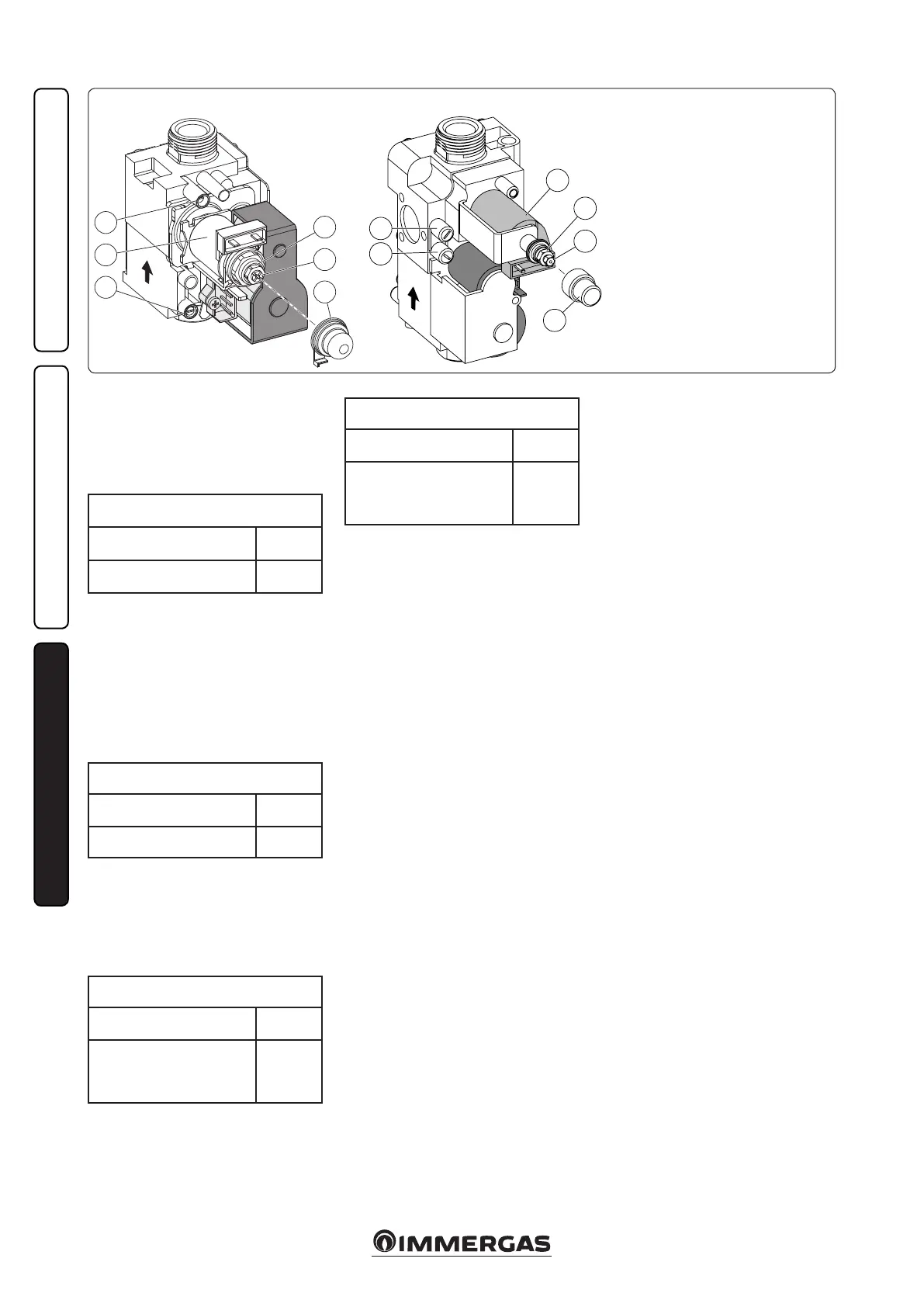
pressure point (part.4 Fig.3-3), keeping to the
pressure value given in the table (Par. 3.18) ac-
cording to the type of gas for which the boiler
is prepared.
SIT 845 GAS valve
Key:
1 - Coil
2 - Minimum power adjustment nut
3 - Maximum power adjustment nut
4 - Gas valve outlet pressure point
5 - Gas valve inlet pressure point
6 - Protection hood
VK 4105 M GAS valve