9
STVP ed 02/06 VICTRIX Plus
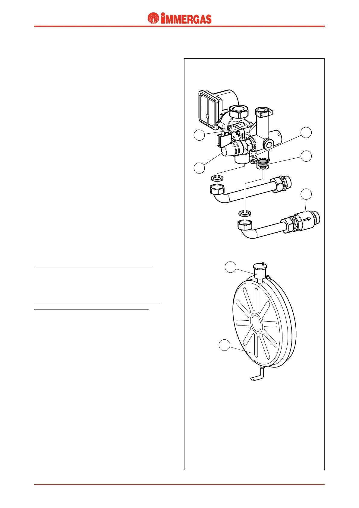
Safety devices and checks.
Adjustable system by-pass (3).
is device guarantees the circulation of water in the primary
circuit (between delivery and return) even when it would be
prevented by the high resistance of the system.
It is mounted on an enbloc and can be adjusted by means of
a screw accessible from the bottom part of the valve support
plate.
No-water pressure switch (1).
is detects the pressure difference at the ends of the circula
-
tor.
It is housed in the enbloc and connected to a microswitch that
prevents the burner working if the pump is blocked or there
is no water in the boiler circuit.
It prevents the main exchanger from overheating.
Automatic air vent (6).
It automatically expels any gaseous substances from the boiler
circuit.
It is screwed to the water side of the expansion vessel.
3-bar safety valve (2).
It is located at the front of the 3-way enbloc and prevents safety
pressure being exceeded in the circuit (3 bar).
When this valve trips it causes water to exit from the delivery
pipe.
One-way valve (4).
(up to serial number 2279840 for VICTRIX 20 Plus)
During the d.h.w. mode it prevents natural circulation starting
in the central heating system.
“Europa” type one-way valve (5).
(from the serial number 2279841 for VICTRIX 20 Plus)
(from the start of production for VICTRIX 27 Plus)
During the d.h.w. mode it prevents natural circulation starting
in the central heating system.
It is housed at the end of the system delivery pipe where the
boiler’s connection unit is located.
Expansion vessel (7).
It offsets volume variations resulting from the water being
heated thus restricting pressure variations.
It is mounted at the back of the appliance and connected to
the pump by means of a coupling tube.
It has a capacity of 8 litres and a 1 bar pre-load pressure.
6
7
Technical Documentation
Technical Documentation