8
STVP ed 02/06 VICTRIX Plus
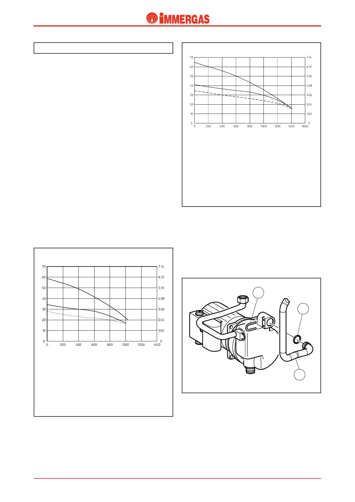
Primary circuit (boiler circuit).
Flow litres/h
A = Head available to the system on maximum speed with the by-pass
off (adjustment screw fully tightened)
B = Head available to the system on maximum speed (screw tightened
4.5 turns compared to the screw completely loose)
C = Head available to the system on maximum speed with the by-pass
open (adjustment screw completely loose)
A
B
C
Head (kPa)
Flow litres/h
A
B
C
A = Head available to the system on maximum speed with the by-pass
off (adjustment screw fully tightened)
B = Head available to the system on maximum speed (screw tightened
4.5 turns compared to the screw completely loose)
C = Head available to the system on maximum speed with the by-pass
open (adjustment screw completely loose)
VICTRIX 20 Plus
VICTRIX 27 Plus
Head (m H
2
O)
Head (kPa)
Head (m H
2
O)
2
1
3
e primary circuit with relevant control and safety devices is
triggered each time there is a request for central heating or
domestic hot water.
Operation.
e heat contained in the products of combustion is absorbed
by the pipes of the coil water-gas exchanger fitted in the con-
densation module (14) which, in turn, transfers it to the water
circulating inside thanks to the boiler pump (26).
When the boiler is working only in the central heating mode,
the water is transferred directly into the system while if it is
coupled to the storage tank it can be diverted to inside the
storage tank coil.
is depends on the position of the electric 3-way diverter valve
(5) which, depending on the request, permits flow through the
system delivery (M) and return (R) pipes, or it diverts the flow
to the storage tank coil.
Flow-head graph.
e trend of the curve that represents the flow-head ratio,
depends on how the system by-pass is adjusted. Depending
on the position, it provides the system with a higher or smaller
head.
Circulator.
e circulator works on the primary circuit return and is
located on the brass assembly.
It is connected to the enbloc by means of a threaded connec-
tion while the condensation module and the expansion vessel
are connected by means of coupling pipes (2) and an O ring
(3), locked by special forks (1).
Primary exchanger (see VICTRIX).
Technical DocumentationTechnical Documentation