16
STVP ed 02/06 VICTRIX Plus
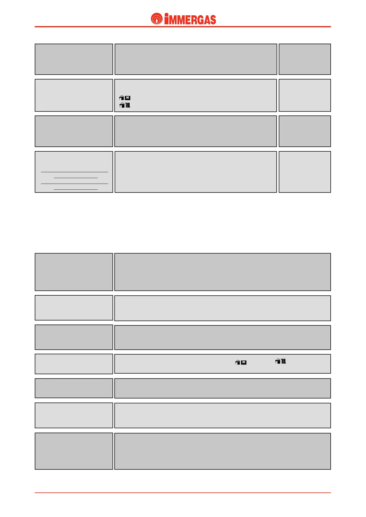
is cuts power to the transformer (230V/24V) of the low-voltage circuit
when the current absorbed is over 315 mA .
It is fitted on the modulating control board.
Transformer fuse
230V / 24V
(T)
315 mA fuse
250 V
Loads.
When the safety temperature is exceeded (100 ºC) this device cuts power
to the gas valve’s main coils.
It is positioned on the delivery pipe at the primary exchanger outlet.
Overtemperature safety device
thermostat
(E4)
Depending on the position:
0: - circuit not powered.
: - d.h.w. and CAR function (optional).
: - d.h.w. and heating function.
Main switch
(S1)
3-position switch
is is controlled by the modulating control board when burner ignition is required.
It controls the devices required for ignition (gas valve, ignition electrodes) and flame detection
(ionisation electrode).
It is located inside the sealed chamber in the bottom right section.
Ignition control unit
(IGN. BOARD)
Clicson twin-con-
tact thermostat
It permits water circulation in the primary circuit.
It is powered by the modulating control board following a d.h.w., heating or antifreeze request.
Circulator
(M1)
ese produce an electric discharge which ignites the air-gas mix.
Electrode E1 is connected to the ignition control unit, while E2 is earthed.
Ignition electrodes
(E1-E2)
is is powered when the main switch is positioned on (summer) or (winter) (see modu-
lating control board operation)
.
Modulating control board
is is a 230 V/ 24 V transformer that supplies the low-voltage adjustment circuit.
It is located inside the sealed chamber in the bottom left section
.
Transformer
(T1)
It diverts the flow of primary circuit water from the heating system to the storage tank coil and
vice versa.
It is powered by the modulating control board.
Electric 3-way diverter valve
(M3)
is is energised by the ignition control unit (IGN. BOARD) when the burner has to be ignited.
It is energised at mains voltage rectified by a diode bridge (U1) inside the gas valve connector.
It lets gas flow to the burner.
Gas valve (Y1)
(main coils)
When the fume safety temperature is exceeded (100 ºC) this device cuts
power to the gas valve’s main coils.
It is positioned on the condensation module close to the draught
diverter.
Fume thermostat
(E6)
(from the serial number 3035590
for VICTRIX 20 Plus)
(from the serial number 2773117
for VICTRIX 27 Plus)
Clicson twin-con-
tact thermostat
Technical DocumentationTechnical Documentation