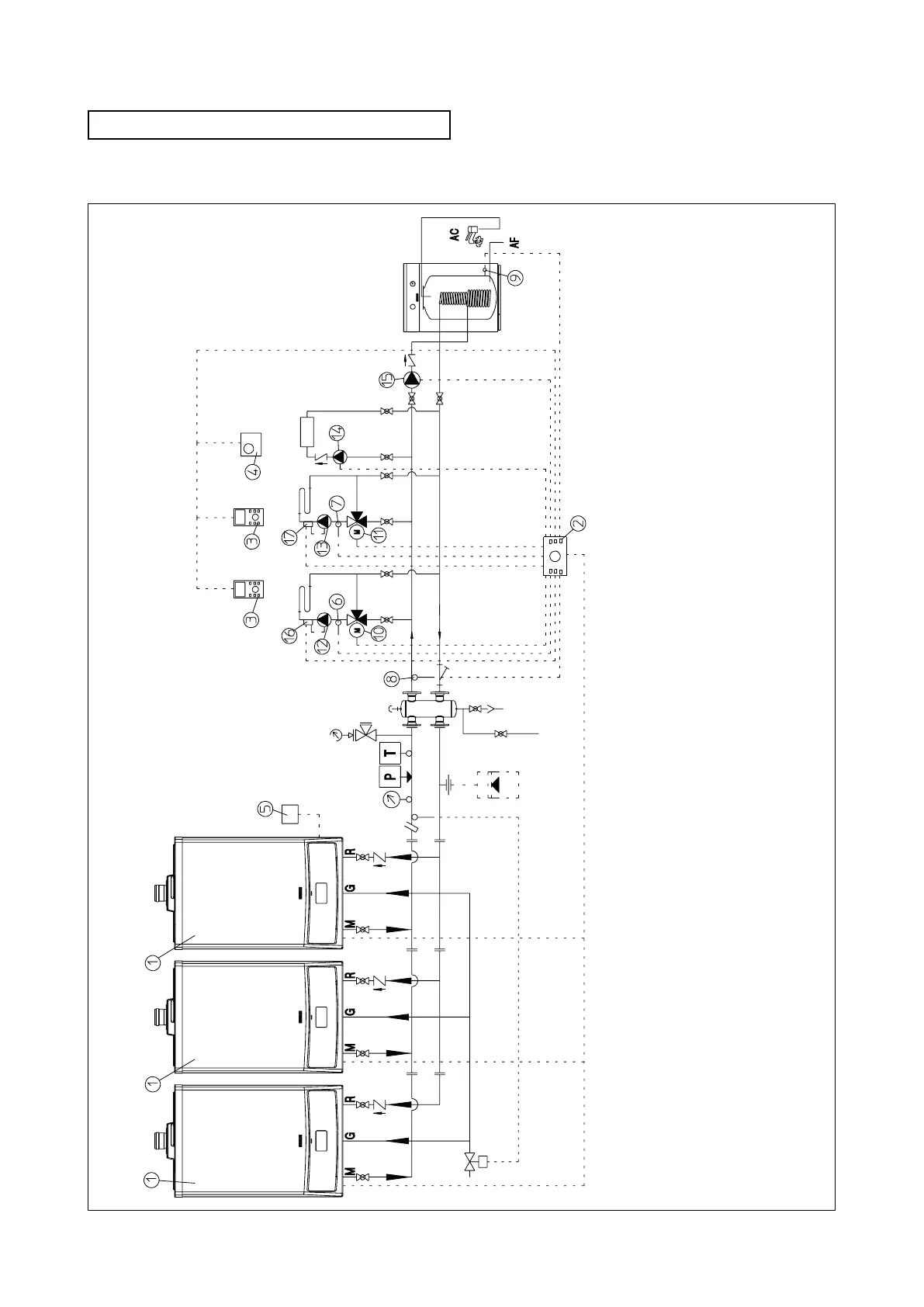
With VICTRIX 50 boiler and cascade regulator it is possible
to connect in cascade up to three boilers as shown in the
hydraulic scheme below:
Conguration for the connection in cascade.
Key:
1 - VICTRIX 50 generator
2 - Cascade and zones regulator
3 - Zone manager
4 - Modulating room thermostat
5 - External sensor
6 - Temperature sensor zone 1 (MC 1)
7 - Temperature sensor zone 2 (MC 2)
8 - Common delivery sensor
9 - Storage tank temperature sensor
10 - Mixer valve zone 1 (MC 1)
11 - Mixer valve zone 2 (MC 2)
12 - Heating circuit pump zone 1 (MC 1)
13 - Heating circuit pump zone 2 (MC 2)
14 - Direct circuit pump zone 3 (HC)
15 - Storage tank supply pump
16* - Safety thermostat zone 1 (MC 1)
17* - Safety thermostat zone 2 (MC 2)
(*) to be used in case of low temperature circuit

 Loading...


