9
(A)
(B)
1-8
INSTALLERUSER
MAINTENANCE TECHNICIAN
1.9 IMMERGAS FLUE SYSTEMS.
Immergas supplies various solutions separately
from the boilers regarding the installation of
air intake terminals and ue exhaust, which are
fundamental for boiler operation.
Attention: the boiler must be installed ex-
clusively with an original Immergas “Green
Range” inspectionable air intake system and
fumes extraction system made of plastic, with
the exception of the C6 conguration, as re-
quired by the regulations in force.
e plastic pipes cannot be installed outdoors,
for tracts longer than 40 cm, without suitable
protection from UV rays and other atmos-
pheric agents.
is system can be identied by an identica-
tion mark and special distinctive marking
bearing the note: “only for condensing boilers”.
• Resistance factors and equivalent lengths. Each
ue component has a Resistance Factor based
on experimental tests and specied in the table
below. e Resistance Factor for individual
components is independent from the type of
boiler on which it is installed and has a dimen-
sionless size. It is however, conditioned by the
temperature of the uids that pass through the
pipe and therefore, varies according to applica-
tions for air intake or ue exhaust. Each single
component has a resistance corresponding to
a certain length in metres of pipe of the same
diameter; the so-called equivalent length,
can be obtained from the ratio between the
relative Resistance Factors. All boilers have an
experimentally obtainable maximum Resistance
Factor equal to 100. e maximum Resistance
Factor allowed corresponds to the resistance
encountered with the maximum allowed pipe
length for each type of Terminal Kit. This
information allows calculations to be made to
verify the possibility of setting up various ue
congurations.
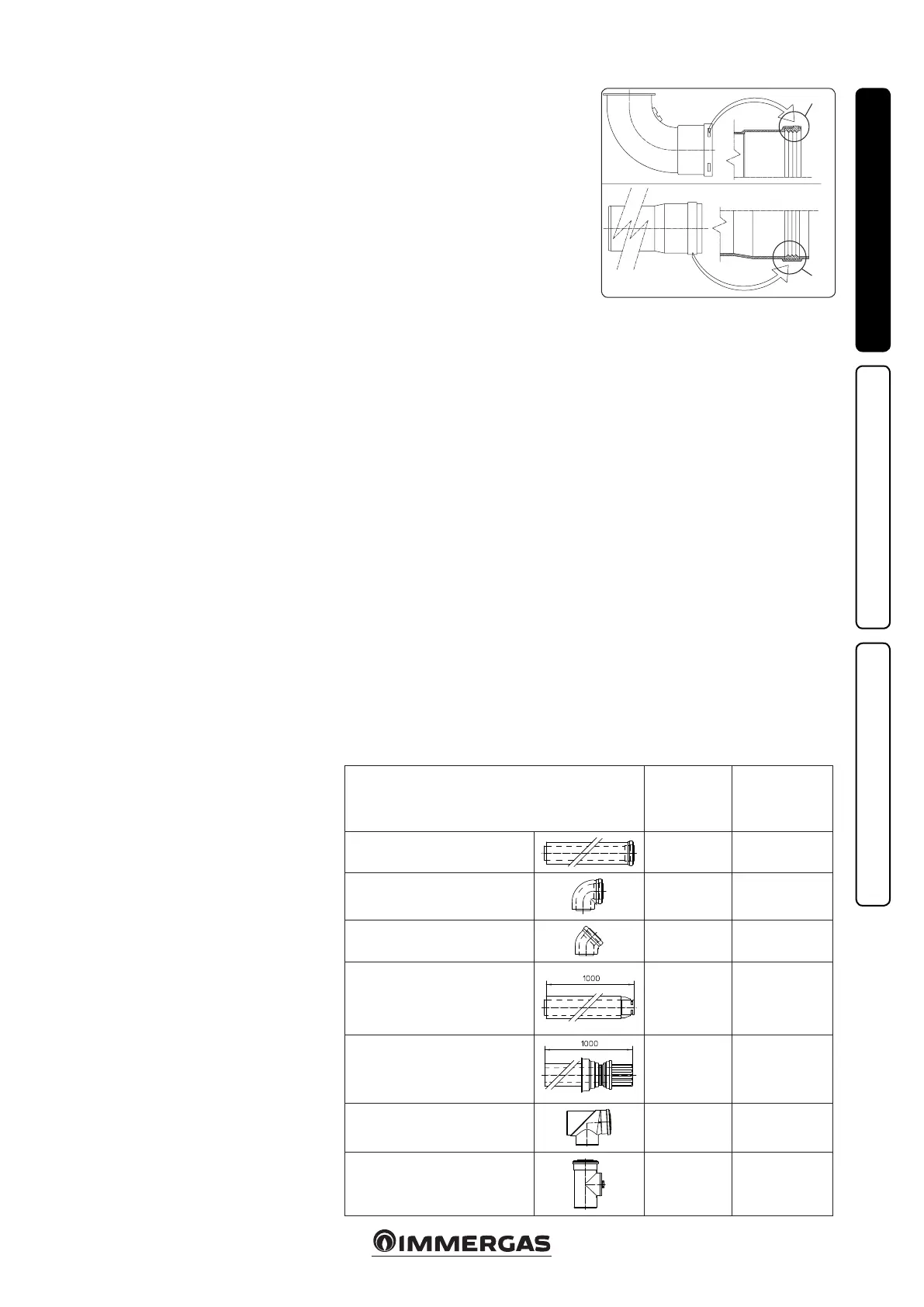
• Positioning the gaskets (black) for “green
range” ue systems. Position the gasket cor-
rectly (for bends and extensions) (Fig. 1-8):
- gasket (A) with notches, to use for bends;
- gasket (B) without notches, to use for exten-
sions;
N.B.: if necessary, to ease the push-fitting,
spread the elements with commonly-used talc.
• Coupling extension pipes and concentric
elbows. To install push-tting extensions with
other elements of the ue, proceed as follows:
Install the concentric pipe or elbow with the
male side (smooth) on the female side (with lip
seal) to the end stop on the previously installed
element in order to ensure sealing eciency of
the coupling.
Attention: if the exhaust terminal and/or
concentric extension pipe needs shortening,
consider that the internal duct must always
protrude by 5 mm with respect to the external
duct.
• N.B.: for safety purposes, do not obstruct the
boiler intake/exhaust terminal, even temporar-
ily.
• N.B.: when installing horizontal pipes, a mini-
mum inclination of 3% must be maintained and
a section clip with pin must be installed every
3 metres.
1.10 TABLES OF RESISTANCE FACTORS
AND EQUIVALENT LENGTHS.
TYPE OF DUCT
Resistance
Factor
(R)
Equivalent length
in m of concentric
pipe Ø 80/125
Concentric pipe Ø 80/125 m 1
2.1
1
Concentric bend 90° Ø 80/125
3.0
1.4
Concentric bend 45° Ø 80/125
2.1
1
Terminal complete with concentric
horizontal intake-exhaust Ø 80/125
2.8
1.3
Terminal complete with concentric
vertical intake-exhaust Ø 80/125
3.6
1.7
Concentric bend 90° Ø 80/125 with
inspection
3.4
1.6
Stub pipe with inspection Ø 80/125
3.4
1.6
 Loading...


