35
INSTALLERUSER
MAINTENANCE TECHNICIAN
3-13
3.15 3WAY PUMP ANTIBLOCK
FUNCTION OPTIONAL.
e boiler has a function that starts the pump
and 3-way valve at least once every 24 hours for
the duration of 20 seconds in order to reduce
the risk of the pump becoming blocked due to
prolonged inactivity.
3.16 RADIATORS ANTIFREEZE
FUNCTION.
e boiler has a function that makes the pump
start when the system ow water reaches 8 °C. If
the system ow water is at a temperature below
5 °C, the boiler starts to operate until it reaches
approximately 16 °C.
3.17 ANTIHUMIDITY ELECTRODE
FUNCTION.
With cascade installations combined with their
relative ue manifold kits with ue adjusting
devices, humidity may develop on the electrodes,
causing them to fail. Avoid the formation of
humidity by enabling this function (by setting
a value other than 0), which turns the fan on
at the speed set in parameter “P11” (5 minutes
on and 5 minutes o). e function is active
when the burner is o and the ow NTC probe
temperature reading is greater than 35°C. e
function is disabled when the temperature drops
below 30 °C.
3.18 INLET 0 ÷ 10 V.
e microprocessor has an analogue 0 ÷ 10 V
inlet (“Y” and “Z” terminals Fig. 1-4) that enables
the boiler to be controlled from the outside.
By setting the “P37” parameter, it is possible
to set-up the inlet by choosing the functioning
mode between temperature set and power set.
e inlet activates a 2 V (minimum) request and
increases it proportionally up to 9.5 V (max-
imum). e request is deactivated below 1 V.
Notes:
- If “P37” is set at “0”, it is not active when the
boiler is in “stand-by” or “summer” mode.
e calculated set is dened within the “P02”
÷ 20 °C range. e maximum and minimum
temperature within the set is limited by “P01”
and “P32”.
- If “P37” is set on “1” it is always active. It is not
limited by the “P08” and “P09” parameters
and does not have priority over the DHW
request.
- Input voltage = -2.5 ÷ 12.5 V
- Input = 200 μA
- Impedance = > 50 KΩ
3.19 FUNCTIONING WITH COMMON
FLOW PROBE.
With a hydraulic circuit breaker, there must be
a common ow probe (with boiler ow probe
functions) and a pump to be connected down-
stream of the plant.
e probe must be connected to terminals “S1”
and “S2” and parameter “P38” must be set up,
whereas the pump must be connected to termi-
nals “C” and “D”.
If there is a DHW circuit, it can be connected
via an external 3-way to be connected to “IT”,
“IS” and IK terminal, or use a suitable pump to
be connected to “IT” and “IK” terminals. e
DHW circuit has priority over the heating circuit.
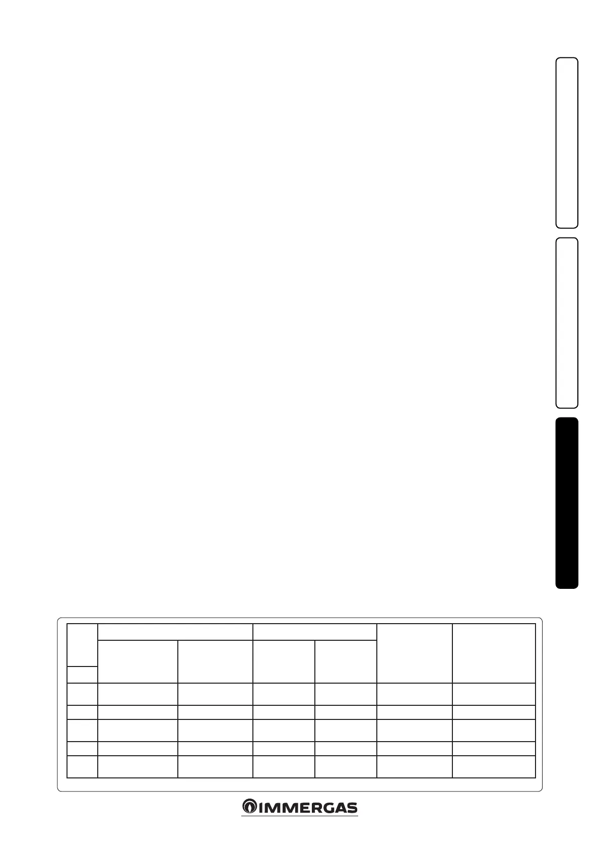
Please refer to chart Fig. 3-13 for the correct
conguration.
3.20 AUTODETECTION.
This function enables the association of the
display board to the boiler’s P.C.B. In addition,
in case of “simple cascade” installation, it enables
the detection and combination of cascade boilers.
Turn the boiler on, programme it according to
your needs, press and hold the “-” (Fig. 2-1 ref.
2) button down until “AUTO” appears, then press
“RESET” until “bu 1” appears.
3.21
SIMPLE CASCADE MAX. 2 BOILERS
It is possible to create a “simple cascade” by
directly connecting two boilers.
e two boilers turn on alternatively based on
the plant’s requirements.
Carry out the connection as indicated in the
diagram (Fig. 3-6). With this configuration,
there must be a common flow probe on the
thermal plant, see the chart (Fig. 3-13) for the
possible options.
In order for the system to recognise the two
boilers, you must activate the Autodetection and
make sure both boilers are on.
ey are associated when “bu 2” appears on
the Master boiler and “SLA 2” appears on the
Slave boiler.
From this moment on, all programming is car-
ried out on the Master boiler, while the “SLA 2”
caption always appears on the Slave boiler, except
in case of anomaly.
e customised parameters of the Master boiler
are automatically replicated on the Slave boiler.
Warning: it is not possible to combine the cascade
and zone regulator to the plant in this case. It is
possible to connect an On/O room thermostat
or use the 0 ÷ 10 V inlet (which must only be
connected to the Master) to control the plant.
N°
boilers
“P38” parameter “P17” parameter
Common ow probe Boiler ow probe
Common ow
probe present = 1
Common flow probe
absent = 0
DHW pump
(downstream the
distribution ma
-
nifold) = 1
3-way valve = 0
1 x x No
Domestic hot water
Central heating
1 x x Central heating Domestic hot water
1 x x
Domestic hot water
Central heating
Just as limit thermostat
2 x Not admitted Central heating Just as limit thermostat
2 x xx
Domestic hot water
Central heating
Just as limit thermostat






 To Next Page