VICTRIX PRO V2 EU
113
1
2
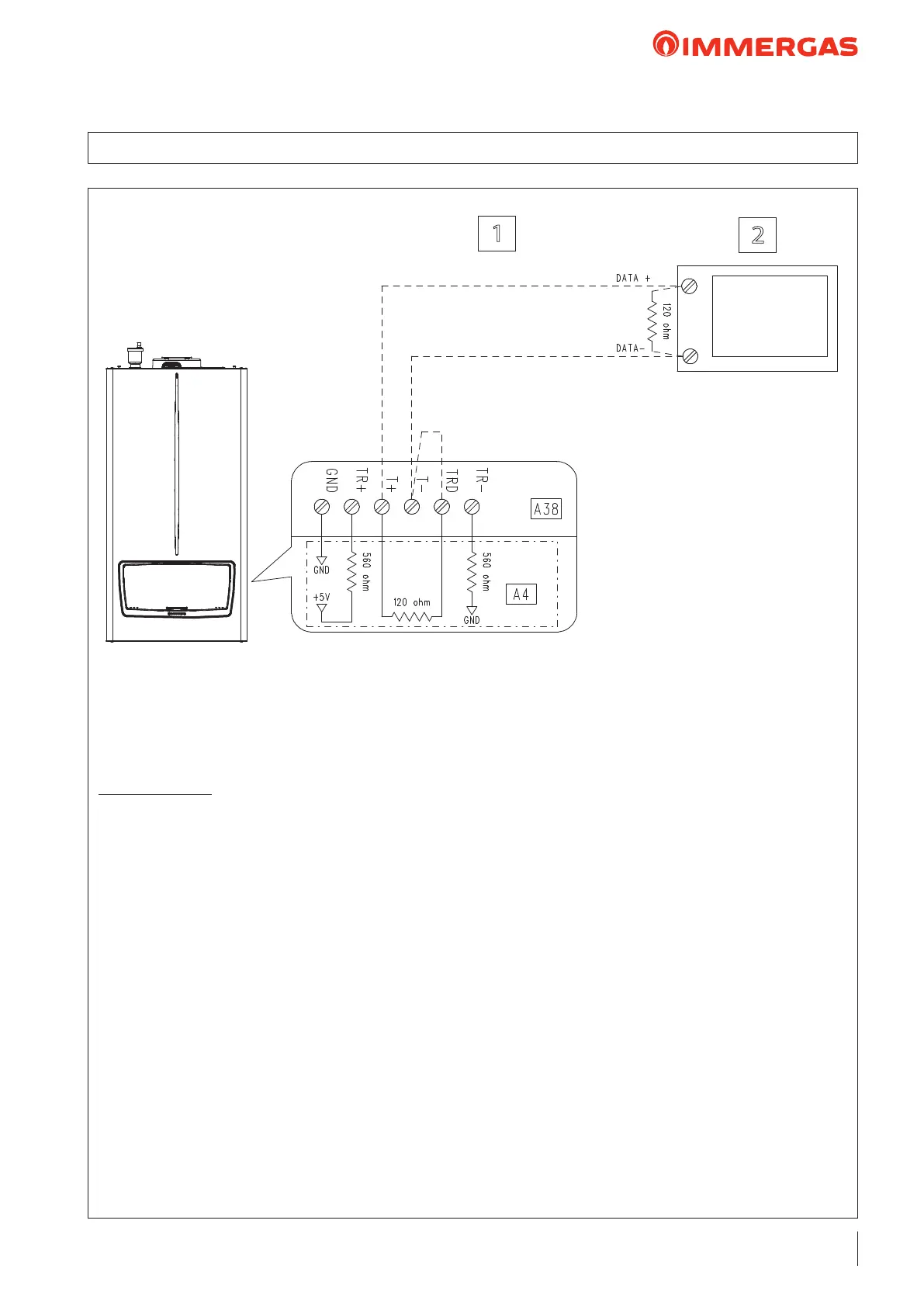
Technical Notes:
- e jumper X40 must be removed.
- e Modbus parameters can be found in the 'TECHNICIAN/SYSTEM SETTINGS/Modbus parameters'
menu.
- e parameter 'Heating request type' must be set as 'Room thermostat setpoint' (default value).
- It is possible to connect the following sensors to the device and read them via BUS:
- System ow probe (B1-2);
- External probe (B4);
- DHW probe (B2);
- DHW Contact or ermostat (S50).
- e DHW can be managed locally (appropriately congure the 3-way valve via the parameters in the "Relay
settings" menu).
- BMS: a pull-up resistance and a pull-down resistance must be present on the bus.
- In the diagram, it is assumed that the two pull up and pull down resistances are already present in the external
appliance (for this reason, TR+ should not be connected with T+ and TR- with T-).
- e resistance (120 ohm) is required on both sides of the BUS (bridging between terminals 'TRD' and 'T-' and
adding the 120ohm resistance, BMS device side, is the responsibility of the installer).
Key:
A4 - Display board
A38 - Connection card (signals)
1 - Cable type: twisted pair (20 / 22 AWG)
2 - BMS (modbus master) (optional)
26.18 WIRING DIAGRAM: CONNECTION TO BMS SYSTEM
 Loading...