VICTRIX PRO V2 EU
114
2
3
3
4
5
6
≤ 2 m
≤ 2 m
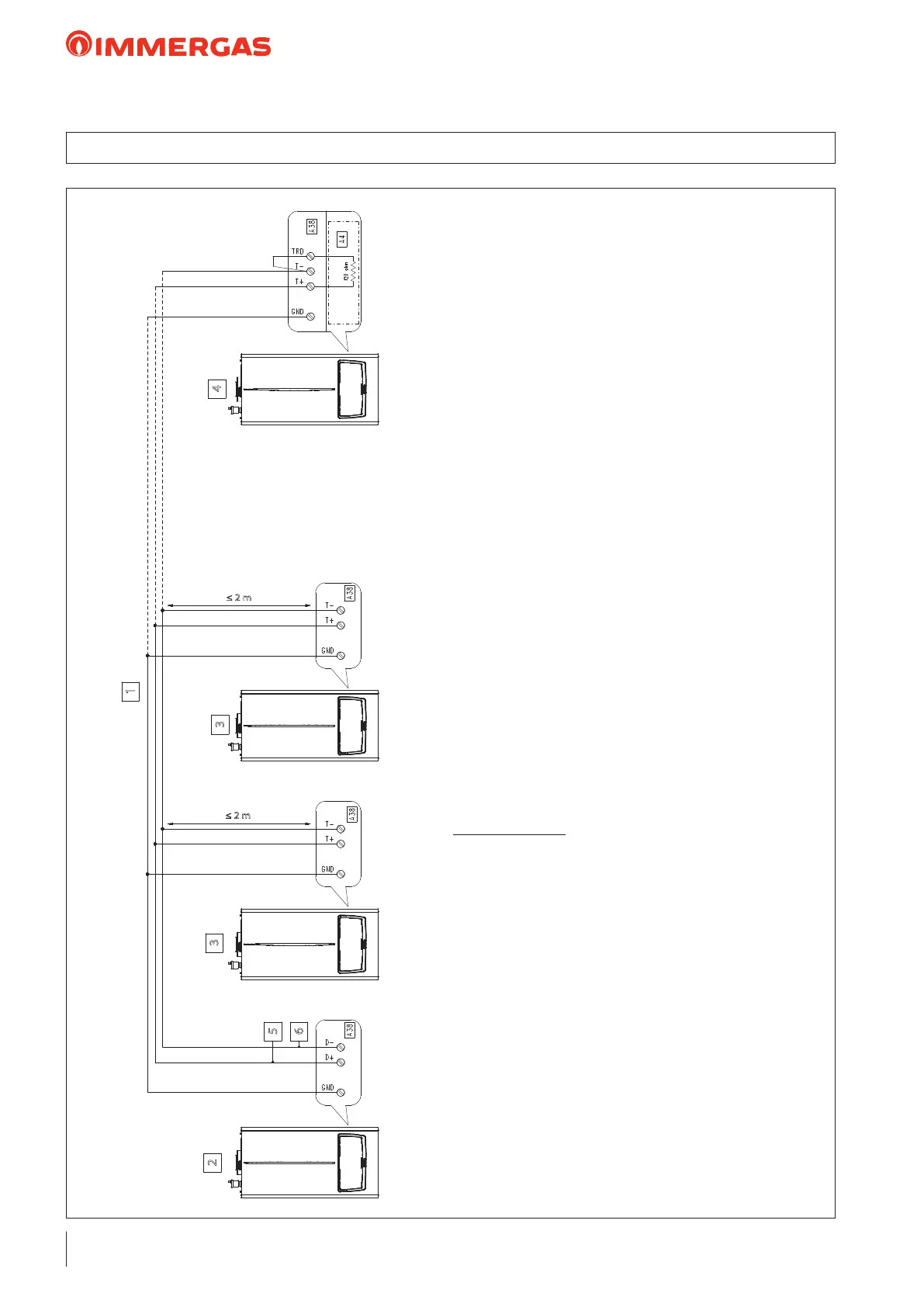
Technical Notes:
- e jumper X40 must be removed.
- e communication BUS between the devices of the
simple cascade is via Modbus protocol (RS485).
- e Modbus parameters, which can be congured
via "MENU", have no eect on the simple cascade
but serve for the BMS.
- In one pair of the twisted pair, connect the 'Data +'
and 'Data -' signals, and in the other pair, connect
the 'GND'.
- e jumper between "TRD" and "T-"terminals is set
up by the Installer (the 120ohm electric resistance is
already on the generator).
26.19 WIRING DIAGRAM: SIMPLE BUS CASCADE CONNECTION
Key:
A4 - Display board
A38 - Connection card (signals)
1 - Cable type: 2 x twisted pair (20 / 22 AWG)*
2 - Master Boiler
3 - Slave Boiler
4 - Slave boiler (last)
5 - Data +
6 - Date -
 Loading...