VICTRIX PRO V2 EU
129
e terminal board of the cascade and zone regulator has
network, low-voltage and signal connections.
Some complementary products, intended to operate the
thermal system, will be connected to the relevant terminals
on the terminal board of the same cascade and zone regulator.
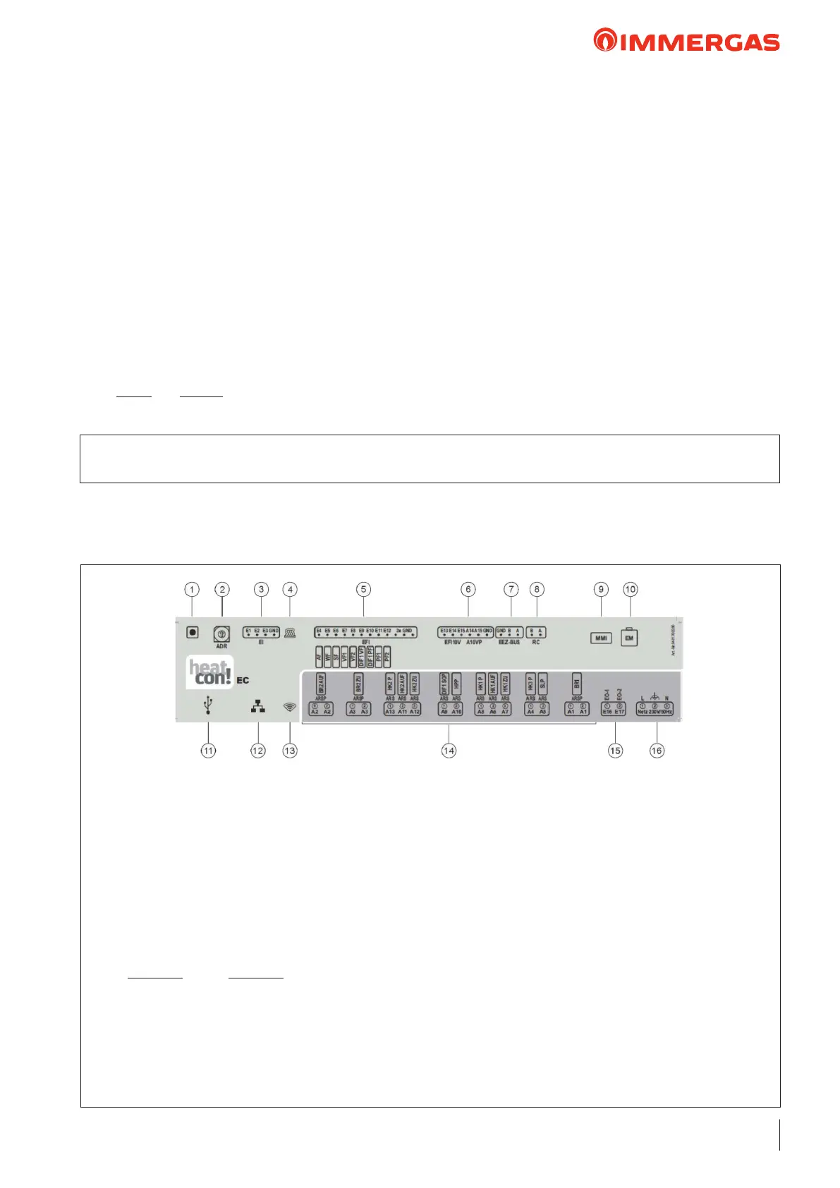
11 - USB connection: to be used to connect the compo-
nents of the 2.0 VICTRIX PRO V2 EU Remote man-
agement kit (initial conguration instead of using
the Cascade and zone regulator, at the connection
via Internet browser)
12 - Network connection (Ethernet, RJ45): to be used
for the initial conguration via Internet browser,
for Remote management and to upgrade heatcon!
rmware
13 - “Network” LED: displays the status of the Internet
connection
14 - Outputs (230V AC): connect the pumps and valves
here (ARS relay terminal N.O. contact – LINE; ARSP
relay terminals N.O. contact)
15 - Digital inputs (230V AC): input opto isolator to count
operating hours
16 - Electric power supply: 230 V ±10 %, 50 Hz
30.2 CASCADE AND ZONE REGULATOR
DIAGRAM OF CONNECTIONS AND TERMINALS
• set the operation parameters:
- functioning times,
- system mode,
- DHW,
- direct circuit, mixed 1, mixed 2,
- date and time;
• display, via self-diagnosis system, of any functioning anom-
alies with error codes;
• show the date, time, day of the week and the boiler temper-
ature on the display,
• the regulator has a specic section for setting the solar system
parameters.
• the regulator board features specic terminals for the vari-
able inputs and outputs, that need to be used based on the
specicity of the system.
Variable inputs
- the variable inlets can be used to send a dry contact of request
from one or more on/o room thermostats (the thermostats
can then control, for example, zone pumps, satellite substa-
tions, etc through relay boxes; when the thermostat calls, it
energises a relay which makes the pump/satellite substation
start up, and it also sends an output dry contact to the cascade
and zone regulator on the variable input);
- with a set of boilers, the common ow probe always uses a
variable input;
Variable outlets
- the solar pump always uses 1 variable outlet;
- the recirculation pump always uses 1 variable outlet.
KEY:
1 - Button: not used
2 - Address selector: used when there are 2 or more
heatcon!
3 - Digital inputs: input for pulse sensor
4 - “Control” LED: displays the status of the connected
appliance and BUS communication
5 - Temperature sensor inputs: connect the analogue
temperature sensors here
6 - Analogue inputs/ Analogue outputs (0-10V)
7 - Connection Bus of the appliances
8 - Bilar Bus h2B for zone manager: connect the heat-
con! zone manager(s)
9 - MMI Heatcon! connection: connect the control
interface of the Cascade and zone regulator here
10 - System Bus for heatcon! EM 100: connect the heat-
con! EM 100 expansions here
 Loading...