VICTRIX PRO V2 35 - 55 - 60 - 68 - 80 EU
49
G2"1/2
G2"1/2
2
G2"1/2
G2"1/2
G3/4"
14
25 6
11 10
4
1
9
13
3
7
12
8
13
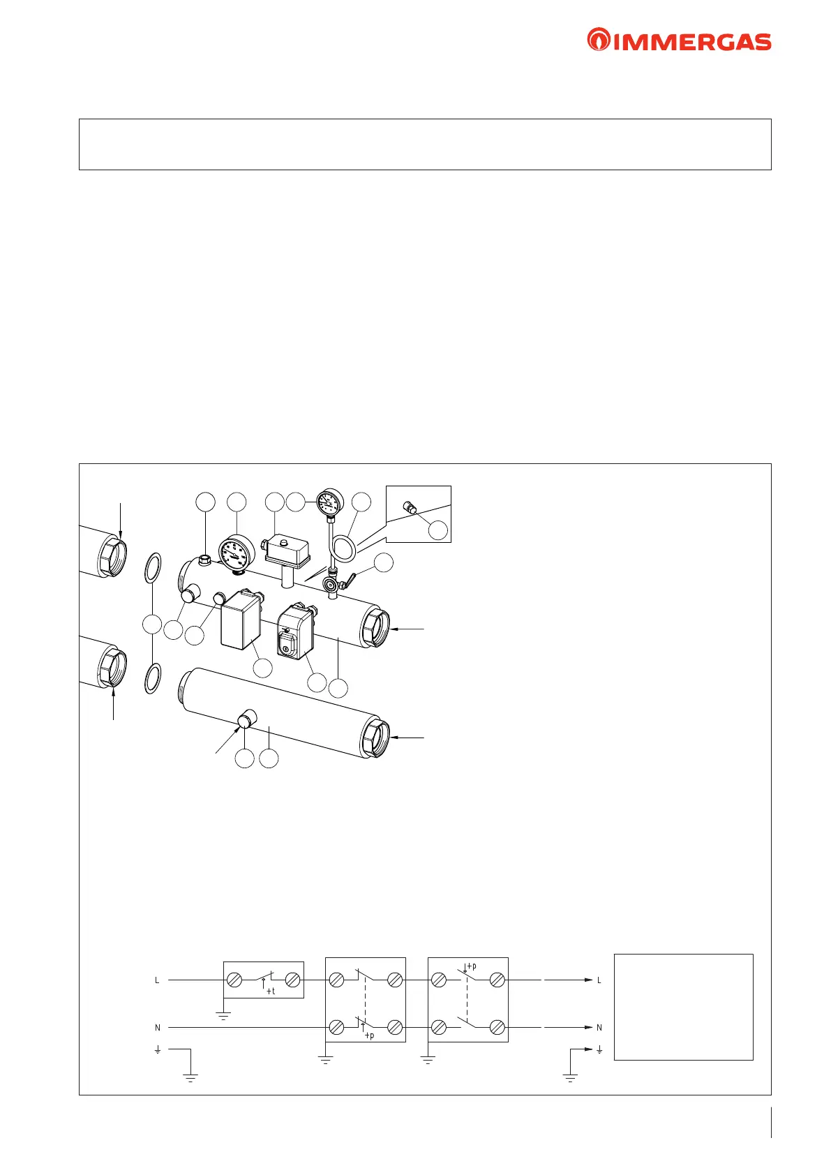
KEY:
1 - 72x55x2 gasket
2 - ermometer pocket
3 - Brass plug G1/2" M (possibly with F.S.O.V.
tting)
4 - INAIL type-approved pressure gauge-holder
cock
5 - INAIL-approved thermometer (scale 0-120 °C)
6 - INAIL-approved manual reset thermostat
(calibration temperature of 95 °C)
7 - INAIL-approved manual reset pressure switch
(1-5 bar adjustment - 3 bar factory setting)
8 - Insulated return stub pipe L=500 mm
9 - Insulated ow stub pipe L=500 mm
10 - Damper coil
11 - INAIL-approved pressure gauge (0-6 bar scale)
12 - INAIL-approved minimum pressure switch
(0.5-1.7 bar adjustment - 0.9 bar factory setting)
13 - Brass plug G3/4" M
14 - Brass plug G1/4" F
M - System ow
R - System return
Safety ther-
mostat
Electrical connections diagram for INAIL safety device kit for boilers in set conguration
Safety pres-
sure switch
Minimum pressure
switch
e modular boilers, i.e. appliances comprised of multiple
modules set up by the manufacturer to operate in cascade
(set) with an original Immergas hydraulic manifold kit, must
be considered a unique generator, which assumes the serial
number (factory number) of the thermal module nearest to
the
INAIL
safety devices. It is therefore possible to ank up to
5 modules, with a unique INAIL safety kit.
With outdoor installation it needs to be protected using the
IPX4D protection box kit for set boiler conguration INAIL
safety devices, code 3.024038, or nonetheless protected from
the elements based on its electrical protection rating.
Immergas S.p.a. declines all liability whenever the installer does
not use the devices and INAIL-approved Immergas original kits
or uses them improperly.
e sensitive elements of the INAIL safety devices must be set
up as described in the installation instructions, in compliance
with the provisions set forth in the ''R'' collection.
For INAIL design purposes, by installing the Immergas safety
Immergas, there are already the following type-approved
INAIL devices: Manometer-holder cock, manometer, ther-
mometer, manual reset thermostat, manual reset maximum
pressure switch, and manual reset minimum pressure switch
(the boiler is already equipped as per standard with 4-bar safety
valve and standard draining funnel).
ere is a tting for an expansion vessel on the ow and return
stub pipes.
N.B.: e gure illustrates the INAIL safety device kit instal-
lation with the outlet on the right side, however, it is also to
install the kit with the outlet on the le side.
18 INAIL SAFETY DEVICES KIT G 2 1/2" AT RH/LH FOR VICTRIX PRO V2
35 55 - 60 - 68 - 80 EU MODULES IN SET CONFIGURATION CODE: 3.023955
M
R
To the supply
Single or set boiler
conguration
230 Vac
50 Hz
MAINS