VICTRIX PRO V2 EU
51
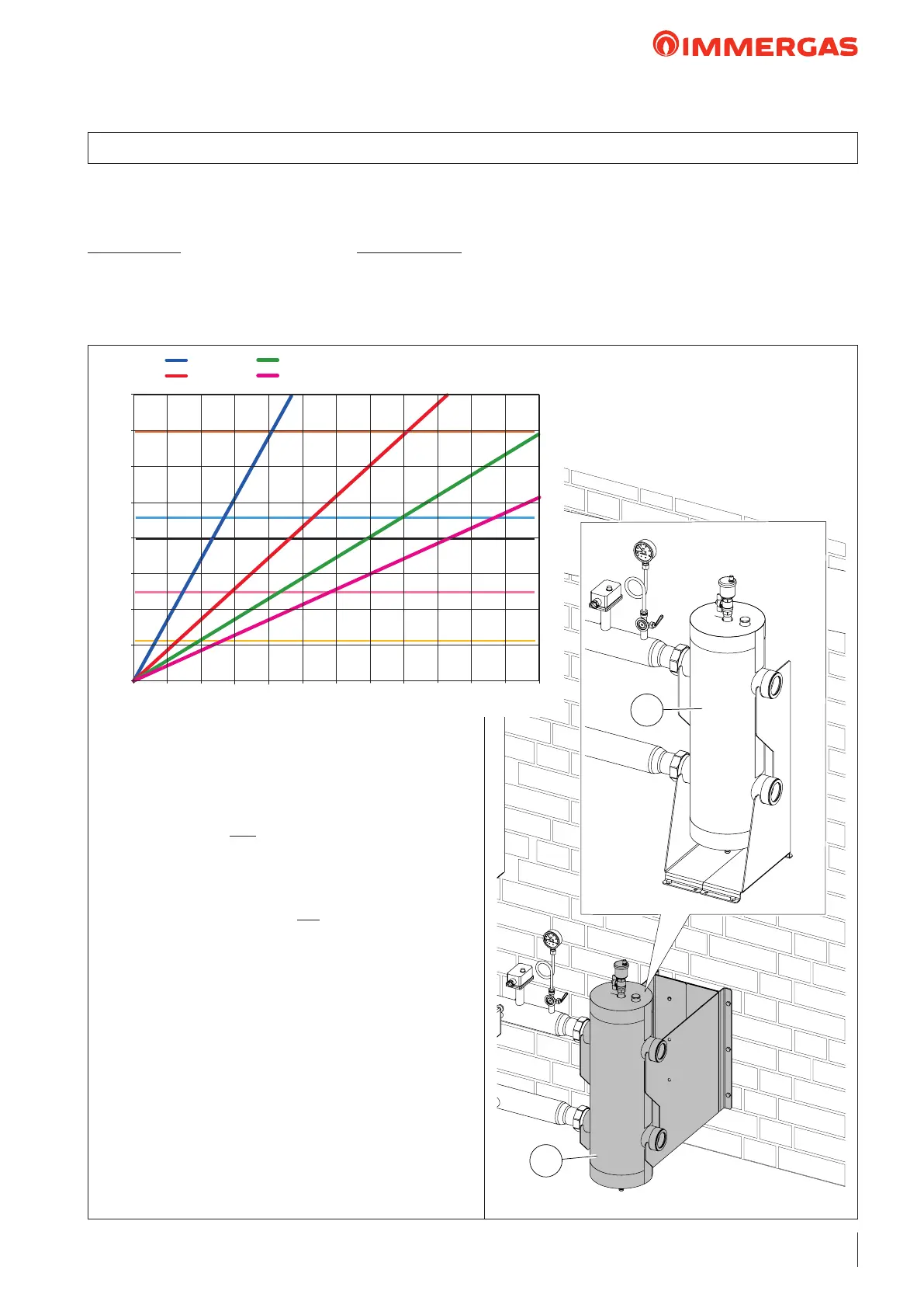
e hydraulic separator, also called compensator, is an open
manifold (1) with puts the ow lines and return lines of 2
or more hydraulic circuits in communication: in this case, a
primary circuit (Generator-Manifold) and a secondary circuit
(Manifold-ermal system).
Circulation is ensured by the generator in the primary circuit,
while there are one or more pumps in the secondary circuit
which, based on the system design, provide the correct tem-
perature dierence (therefore with the right water ow rate)
so as to exchange the output necessary.
It is advisable to include a hydraulic compensator (1) every
time the overall ow rate required by the system is greater than
what the boiler is able to supply. e maximum ow rate at
the inlet is the generally adopted sizing method (see the graph
below for separator selection).
1
1
e chart shows the Flow rate, power and temperature dif-
ference curves between system ow and return, required for
correct dimensioning
Example:
let us assume you have two VICTRIX PRO V2 120 EU with a
heat output of 243.4 kW (209,364 kcal/h) for 50/30 °C.
1st case: the design ∆T of the system is 20 °C, with a ow
rate of 10,468 l/h. e ideal manifold is the following 200 kW
separator kit ( hereinaer called kit) code 3.021377 (see the
area between the horizontal yellow line and the pink one).
2nd case: the design ∆T of the system is 15 °C, with a ow
rate of 13,957 l/h. e manifold that can be used is the 350
kW kit, code 3.023965 (we are at the limit of the pink and
black horizontal line).
3rd case: the design ∆T of the system is 10 °C, with a ow
rate of 20,936 l/h. e manifold that can be used is the 400
kW kit, code 3.021378 (see the area between the horizontal
black line and light blue one).
4th case: the design ∆T of the system is 7 °C, with a ow rate
of 29,909 l/h. e manifold that can be used is the 600 kW
kit, code 3.023962 (see the area between the horizontal light
blue line and the orange one).
19 HYDRAULIC SEPARATOR KIT FOR MODULES IN SET CONFIGURATIONOPTIONAL
0
5
10
15
20
25
30
35
40
Portata m
3
/h
Potenza - kW
0 50 150100 250200 300 350 400 450 500 550 600
∆T = 5 °C
∆T = 10 °C
∆T = 15 °C
∆T = 20 °C
350 kW
200 kW
100 kW
400 kW
600 kW
Power – Kw
Flow rate m
3
/h