VICTRIX PRO V2 EU
93
25.6 RESIDUAL HEAD AVAILABLE ON CHIMNEY OPENING
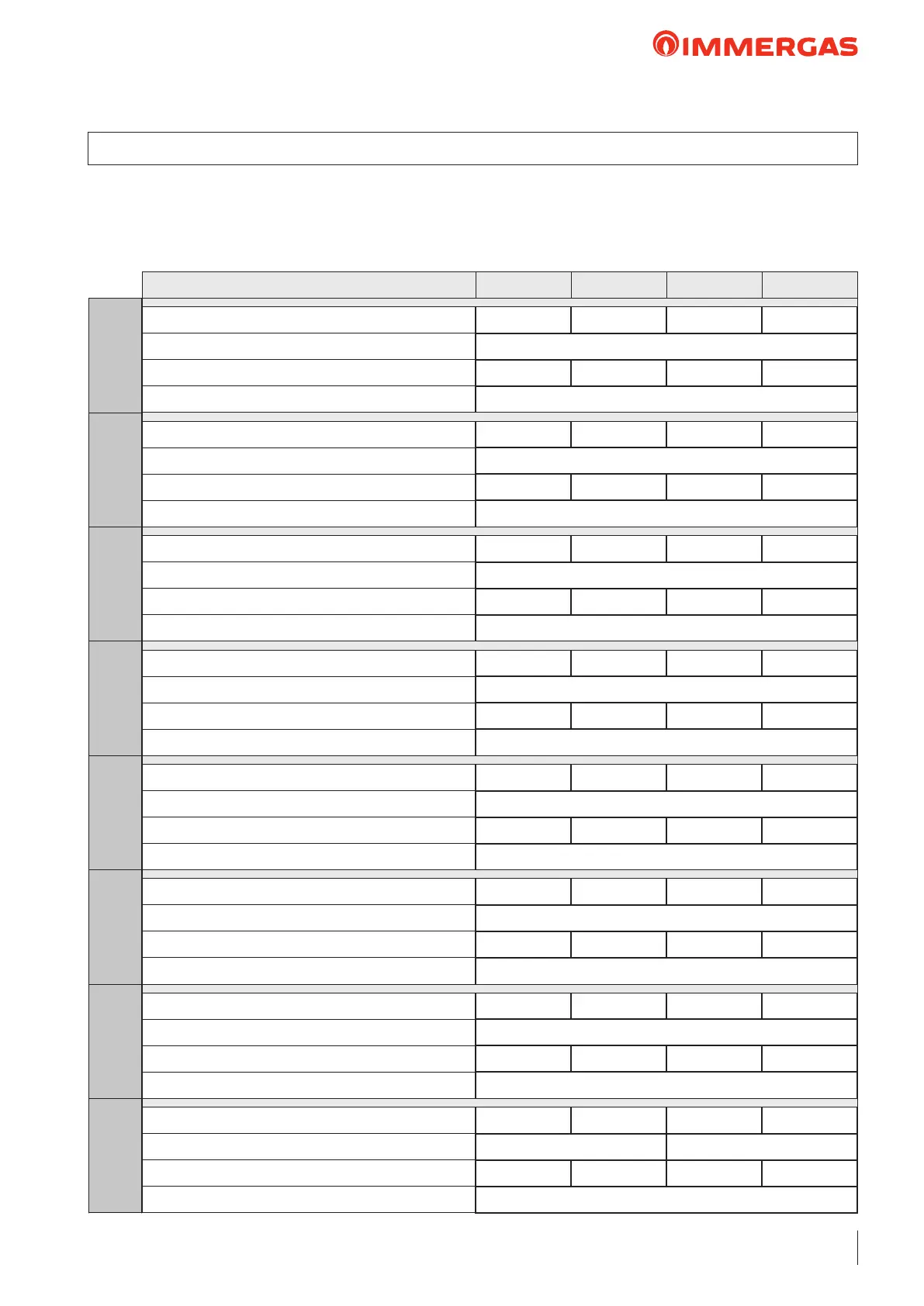
Number of modules in set conguration:
N° 2 N° 3 N° 4 N° 5
Nominal heat input (kW) 69,8 104,7 139,6 174,5
Flue diameter (mm) Ø 160
Residual head at the ends of the cascade (Pa) 13,0 28,0 50,0 78,0
Parameter “P26” Min Fan Speed (rpm) 1700
Nominal heat input (kW) 102,0 153,0 204,0 255,0
Flue diameter (mm) Ø 160
Residual head at the ends of the cascade (Pa) 27,0 61,0 109,0 170,0
Parameter “P26” Min Fan Speed (rpm) 1700
Nominal heat input (kW) 102,0 153,0 204,0 255,0
Flue diameter (mm) Ø 160
Residual head at the ends of the cascade (Pa) 27,0 61,0 109,0 170,0
Parameter “P26” Min Fan Speed (rpm) 1700
Nominal heat input (kW) 102,0 153,0 204,0 255,0
Flue diameter (mm) Ø 160
Residual head at the ends of the cascade (Pa) 27,0 61,0 109,0 170,0
Parameter “P26” Min Fan Speed (rpm) 1700
Nominal heat input (kW) 150,0 225,0 300,0 375,0
Flue diameter (mm) Ø 160
Residual head at the ends of the cascade (Pa) 23,0 52,0 93,0 145,0
Parameter “P26” Min Fan Speed (rpm) 1700
Nominal heat input (kW) 186,0 279,0 372,0 465,0
Flue diameter (mm) Ø 200
Residual head at the ends of the cascade (Pa) 11,5 26,0 45,0 71,0
Parameter “P26” Min Fan Speed (rpm) 1500
Nominal heat input (kW) 229,0 343,5 458,0 572,5
Flue diameter (mm) Ø 200
Residual head at the ends of the cascade (Pa) 18,0 40,0 72,0 112,0
Parameter “P26” Min Fan Speed (rpm) 1500
Nominal heat input (kW) 282,0 423,0 564,0 705,0
Flue diameter (mm) Ø 200 Ø 250
Residual head at the ends of the cascade (Pa) 18,0 40,0 70,0 110,0
Parameter “P26” Min Fan Speed (rpm) 1850*
e chimney/ducted pipe which collects the ue gas coming
from the ue manifold, is sized under pressure or vacuum. If
you wish to operate with a pressurised chimney/ducted pipe,
the value of the residual head at the ends of the set - shown
in the table - represents the maximum head loss of the ue
system to guarantee operation of the modules in cascade in
dynamic mode.
VICTRIX PRO V2
150 EU
VICTRIX PRO V2
120 EU
VICTRIX PRO V2
100 EU
VICTRIX PRO V2
80 EU
VICTRIX PRO V2
68 EU
VICTRIX PRO V2
60 EU
VICTRIX PRO V2
55 EU
VICTRIX PRO V2
35 EU
 Loading...