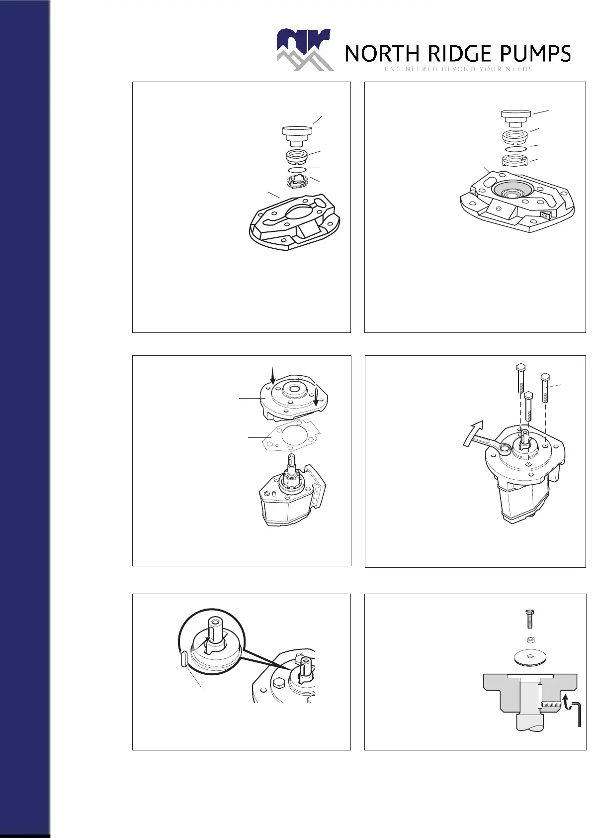
Fig. 27
Fig. 26
Fig. 23
Fig. 25
Fig. 24
Fig. 28
G. xVxx
• Fit the spring unit S7 in place.
Note the position for the Seat
slots and lugs.
(See g 4.)
• Lubricate the O-ring
S2 and put it on the
seat S1. Fit the seat
S1 on top of the
spring unit. Watch
position of the Seat
slots and lugs.
(See g 4.)
• Press the seat gently into the recess in
the front cover 501 with a suitable tool as
shown.
• Turn the front cover 501 up-side down. The
seat shall now remain in the cover.
• Fit the retainer S3
in place. Note the
position for the
retainer lugs and
cover slots.
(See g 4.)
• Lubricate the
O-ring S2 and
put it on the
seat S1. Fit the seat S1
on top of the retainer.
Watch the position of the seat
slots and lugs. (See g 4.)
• Press the seat gently into the recess in the
front cover 501 with a suitable tool as shown.
• Turn the front cover 501 up-side down. The
seat shall now remain in the cover.
H. xTxx
I.
501
506
• Replace the gasket
506.
• Carefully t the Front
cover 501 on the
pump.
J.
451
• Fit the screws
451.
• Tight them crosswise,
step by step to avoid
deformation on bearing
outer ring and seal dam-
ages.
• Turn the shaft to check
that it moves without too
much force.
K.
• Fit the key 113 back in place.
• Press on the shaft cou-
pling to its original position.
• Tighten the stop screw.
L.
501
S1
S2
S7
501
S1
S2
S3
Tool 1
Tool 1
• Install the pump back
into the system and
proceed according
to instructions under
”Start-up” in the
Installation manual.
Product Specification Sheet
X-Cel House, Chrysalis Way, Langley Bridge, Eastwood, Nottinghamshire NG16 3RY
Tel: +44 (0) 1773 302 660 | Email: sales@northridgepumps.com | Website: www.northridgepumps.com