Slew Drives
Installation and commissioning
24
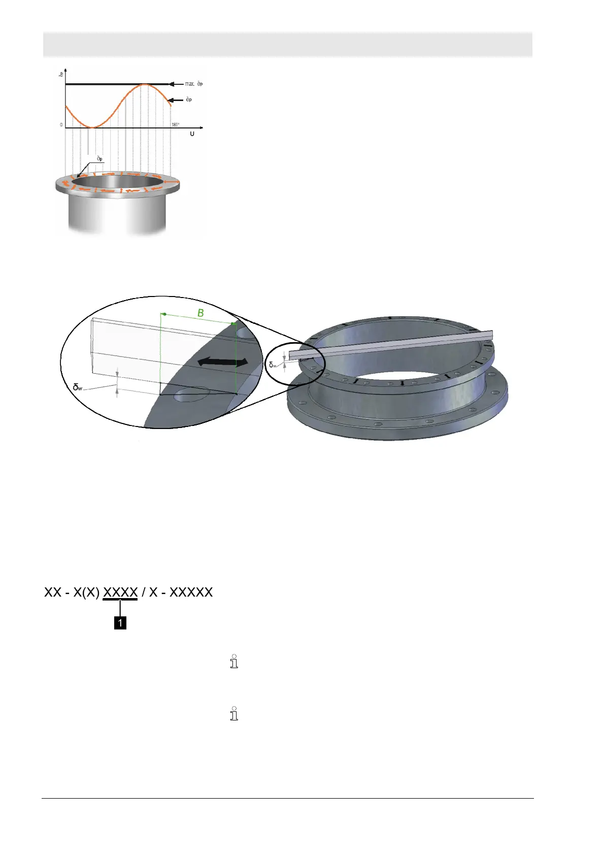
Abb. 14: Permissible flatness deviation of
the mounting structure
δp = flatness deviation
max. δp = maximum flatness deviation
U = circumference
The maximum residual value for flatness deviation δp in
the circumferential direction should only be reached once
on half of the circumference. The gradient must look like a
sinus curve that slowly rises or falls.
Perpendicularity deviation
Fig. 15: Perpendicularity deviation
δw = perpendicularity deviation
B = flange width
The permissible perpendicular deviation δw (tilting) is based on
the actual flange width and should only be half of the values
from the tables below.
Fig. 16: Drawing number
The size of the slew drive (WD-H) or of the running circle diameter
D
L
(WD-L/SP) is indicated in the drawing number at position (1)
and is shown in all documents and the type plate.
For slew drives that are between the specified sizes, always
assume the smaller value. For slew drives that are larger than
the largest diameter, use the largest specified value.
The slew drive must be supported by the mounting structure up
to the diameter specified in the slew drive drawing.