Slew Drives
Installation and commissioning
30
2 – 4.5 UNC 1239 278538
2 1/4 – 4.5 UNC 1608 361493
2 1/2 – 4 UNC 1981 445347
2 3/4 – 4 UNC 2442 548984
Tab. 11
1)
F
M
for hydraulic bolt-tensioning cylinder pretensioned to 85% of
yield strength
5.3 Installing the slew drive
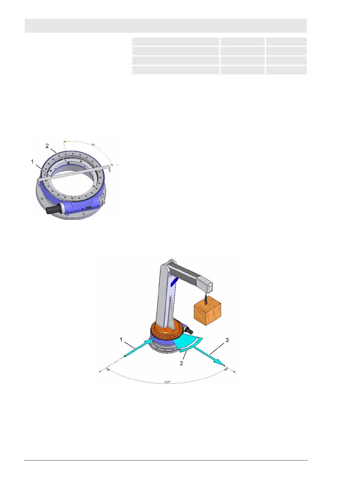
5.3.1 Hardness gap
Fig. 19: Hardness gap marking
The hardness gap occurs with the raceway hardening and is
located between the end and the beginning of the hardening.
For the WD-L series the hardness gap must be arranged with an
offset by 90° relative to the main load-carrying zone. The hardness
gap is marked by a filling plug or a stamped "S".
1 Main load-carrying zone
2 Filling plug or S-mark
5.3.2 Positioning the slew drive
Fig. 20: Main load-carrying zone
1 Hardness gap
2 Main slewing range
3 Main load-carrying zone
1. Determine the main load-carrying zone.
The main load-carrying zone is that area of the slewing ring
that is subject to the highest load, taking all aggressive forces
and torques, and all occurring load cases into account.