Notice: The controller can only open one solenoid valve at a time,
which is based on the consideration of water pressure. If multiple
solenoid valves are opened at the same time, the water pressure will
be insucient and the water will not be able to ow normally.
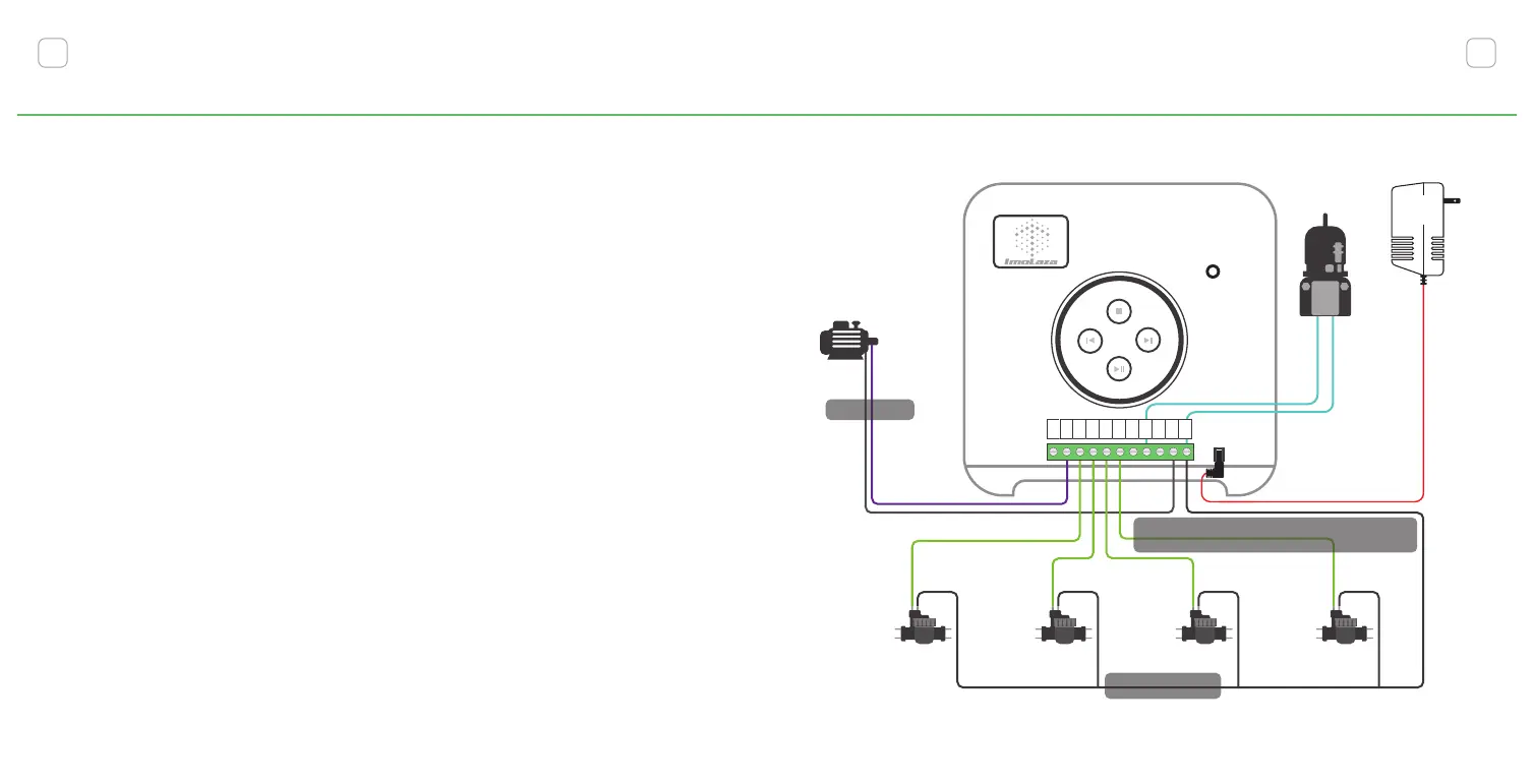
2. 1-8 Zone Wires:
Corresponds to your irrigation zone. Connect sprinkler wires
according to the corresponding labels.
3. Master Valve:
Master valve wires are often labeled "M," "MV," or "Pump." Not all
systems have a master valve. If you have a master valve, wire it into
the "M" terminal, ignore if not.
4. Sensor Wires:
You can connect up to two sensors to your controller using the
"S1," "S2," and 24VAC sensor power terminals.
7
Your Irrigation System
8
RESET
Valve
Valve
Valve Valve
Master Wire
Common Wire
POWER
24VAC
Rain Sensor
M 1 2 3 4 S1 S2
24V
一
AC
AC
COM
COM
24V
+
Sprinkler Wires
Wire from controller to corresponding value
Water Pump
1
2
3
4
5
6
7
8