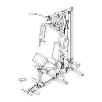
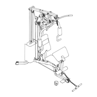
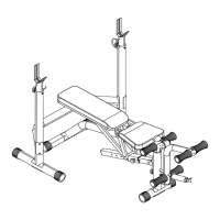
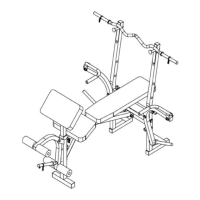
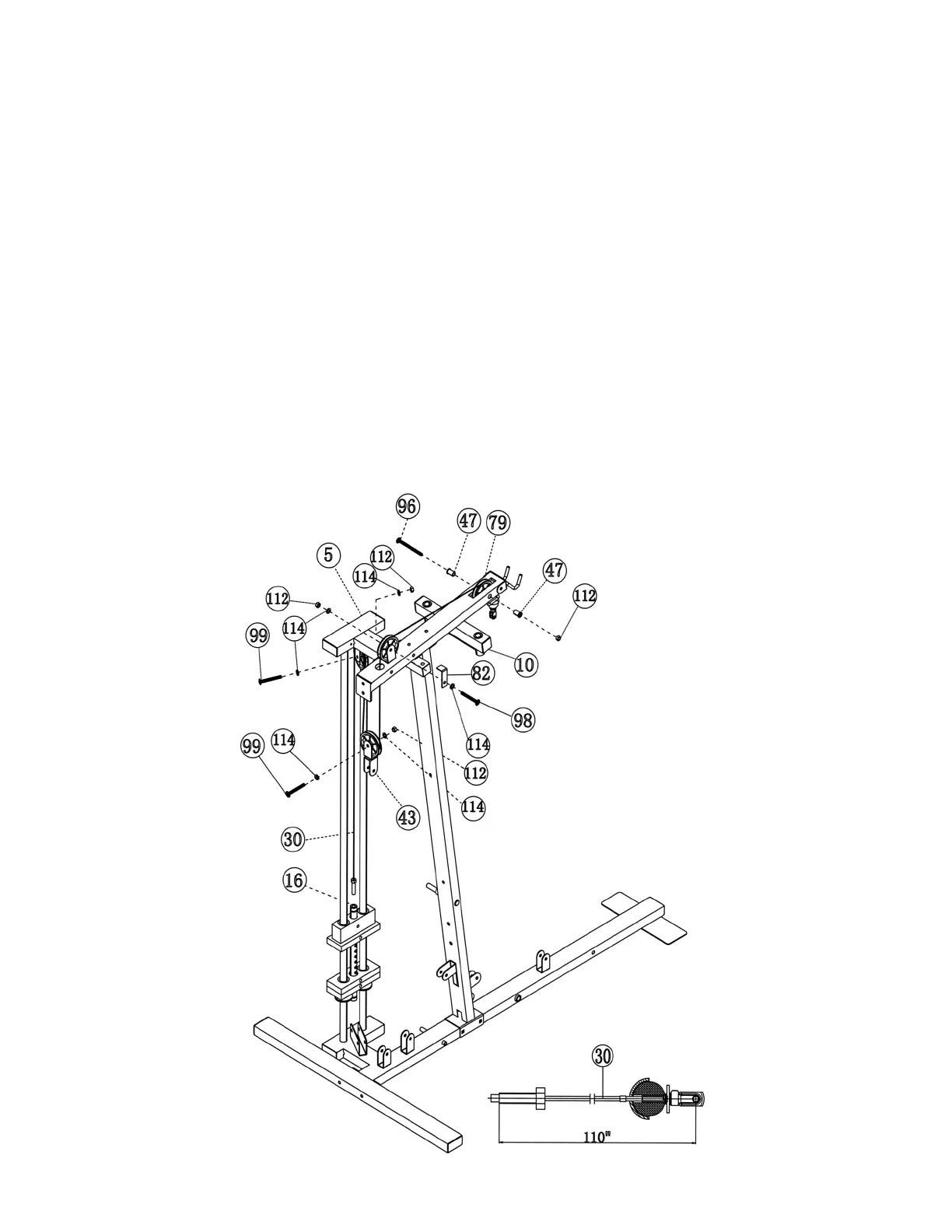
STEP 6 (See Diagram 6 & Cable Loop Diagram)
A.) Insert the 110” Upper Cable (#30) through the opening at the front of the Upper Frame
(#10). NOTE: The Ball Stopper on the Cable should be underneath the Frame. Attach a
Big Pulley (#79) to the opening and secure it with one M10 x 3 ½” Allen Bolt (#96), two
∅7/8” x 1” Bushings (#47), and a M10 Aircraft Nut (#112).
B.) Draw the Cable (#30) towards back of the machine and insert through the opening on the
back of the Upper Frame (#10). Attach a Pulley (#79) to the bracket next to the opening.
Secure it with one M10 x 2“ Allen Bolt (#98), two ∅ ¾” Washers (#114), one 2 1/8” L-
Shaped Bracket (#82), and one M10 Aircraft Nut (#112). The purpose of the Bracket is to
prevent the Cable from coming off the Pulley. Turn the Bracket so the “Bent” is over but
not touching the Pulley.
C.) Attach a Pulley (#79) and a Double Floating Pulley Bracket (#43) to the Cable (#30).
Secure it with one M10 x 1 ¾” Allen Bolt (#99), two ∅ ¾” Washers (#114), and one M10
Aircraft Nut (#112). Let the Bracket hanging for now.
D.) Pull the Cable (#30) upward towards the bracket on the bottom of the Top Socket
Assembly (#5). Attach a Pulley (#79) to the bracket and secure it with one M10 x 1 ¾”
Allen Bolt (#99), two ∅ ¾” Washers (#114) and one M10 Aircraft Nut (#112).
E.) Pull the Cable (#30) downward towards the weight stack. Screw the cable into the top
opening on the Selector Rod (#16).
DIAGRAM 6
11
 Loading...