ASSEMBLY INSTRUCTION
Tools Required to Assemble the Machine: Two Adjustable Wrenches and Allen Wrenches
NOTE: It is strongly recommended this machine be assembled by two or more people to
avoid possible injury.
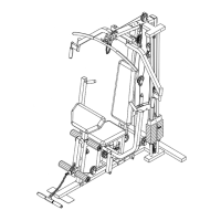
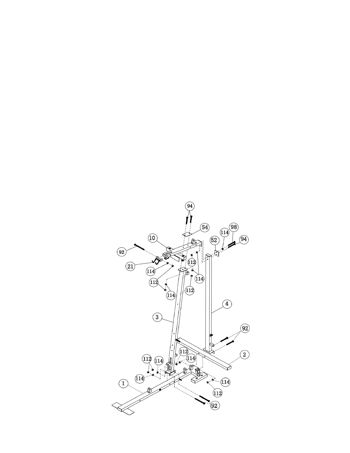
STEP 1 (See Diagram 1)
A.) Attach the Rear Stabilizer (#2) to the back of the Base Frame (#1). Then attach the Rear
Vertical Beam (#4) to the back of the Rear Stabilizer (#2). Align the holes and secure it with
two M10 x 3 ¾” Carriage Bolts (#92), ∅ ¾” Washers (#114), and M10 Aircraft Nuts (#112).
DO NOT tighten all the nuts and bolts yet.
B.) Attach the Front Vertical Beam (#3) to the Base Frame (#1). Secure it with two M10 x 3 ¾”
Carriage Bolts (#92), ∅ ¾” Washers (#114), and M10 Aircraft Nuts (#112).
C.) Attach the Upper Frame (#10) to the top of the Vertical Beam (#3) & (#4). Secure the front with
two M10 x 2 3/8” Carriage Bolts (#94), one 4 5/8” x 3” Bracket (#54), two ∅ ¾” Washers
(#114), and two M10 Aircraft Nuts (#112). Secure the back with a M10 x 2” Allen Bolt (#98),∅
¾” Washer (#114) and 3 1/8” x 3” Bracket (#52) to the top hole. Use one M10x2 3/8” Carriage
Bolt (#94), ∅ ¾” Washer (#114) and M10 Aircraft Nut (#112) to secure the bottom hole.
D.) Attach the Lat Bar Holder (#21) to Upper Frame (#10). Secure it with a M10 x 3 ¾” Carriage
Bolt (#92), ∅ ¾” Washer (#114) and M10 Aircraft Nut (#112).
DIAGRAM 1
4