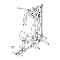
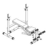
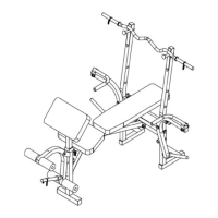
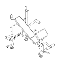
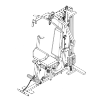
STEP 4 (See Diagram 4)
A.) Slide two Rubber Bumpers (#70) onto the two Weight Plate Guide Rods (#19). Insert the two
Rods into the holes on the Base Frame (#1).
B.) Slide ten Weight Plates (#27) from the top of the Guide Rods (#19) down to the Bumper.
Insert the Selector Rod (#16) into the center hole on the Plates. Slide the Selector Stem
(#26) onto the Guide Rods (#19). Align the hole and secure the Selector Stem (#26) to the
Selector Rod (#16) with a M10 x 1 ½” Allen Bolt (#100).
C.) Attach the Top Socket Assembly (#5) to the top of the Guide Rods (#19). Secure it to the
Guide Rods with two M6 x 1 1/8” Philips Head Screws (#107).
D.) Attach a 5 5/8” x 1 ½” Bracket (#53) to the other side of Upper Frame. Secure the Top
Socket Assembly (#5) to Upper Frame (#10) with a M10 x 3 ¾” Carriage Bolt (#92), to the
back hole. Tighten with a ∅ ¾” Washer (#114) and M10 Aircraft Nut (#112). Insert a M10 x
4 1/8” Carriage Bolt (#91) through the front hole. Slide a Long Chain (#39) onto the Bolt
from the Top Socket Assembly side. Secure them with a ∅ ¾” Washer (#114) and M10
Aircraft Nut (#112).
E.) Attach the Power Booster Frame (#15) onto the axle on the Front Vertical Beam (#3). Secure
it with a M10 x 5/8” Allen Bolt (#102) and ∅ ¾” Washer (#114).
F.) Attach the top of the Air Shock (#44) to the bottom of the Booster Frame (#15). Align the
holes and secure it with one M10 x 1 ¾” Allen Bolt (#99), two ∅ ½” Spacers (#37), one M10
Aircraft Nut (#112).
G.) Attach the bottom of the Air Shock (#44) to the axle on the Base Frame (#1). Secure it with a
M10 x 5 5/8” Allen Bolt (#95) and M10 Aircraft Nut (#112).
H.) Lubricate the inside of the Power Booster Handle Foam Grip (#74) with water. Slide it onto
the handle.
7