ASSEMBLY INSTRUCTION
Tools Required Assembling the Machine: Two Adjustable Wrenches, two Allen Wrenches,
and one Philips Screwdriver. NOTE: It is strongly recommended this machine to be
assembled by two or more people to avoid possible injury.
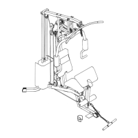
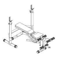
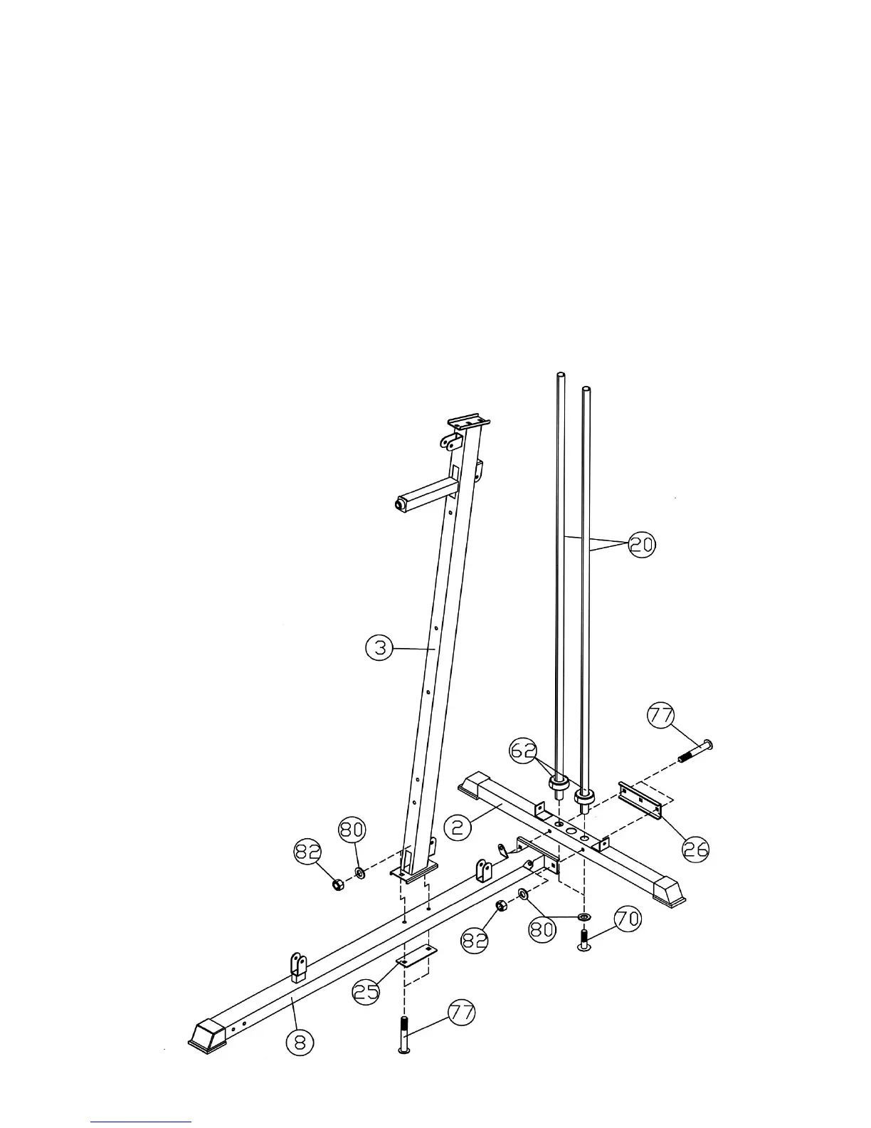
STEP 1 (See Diagram 1)
A.) Attach the Front Vertical Frame (#3) to the Main Base Frame (#8). Secure it with two M10 x 2
¾” Carriage Bolts (#77), one 5 ½” x 2” Bracket (#25), two Ø ¾” Washers (#80), and two M10
Aircraft Nuts (#82). DO NOT tighten all the nuts and bolts yet.
B.) Push two Ø 2 ½” Guide Rod Rubber Bumpers (#62) onto the Guide Rods (#20) from the
bottom. Insert the Guide Rods into the holes on the Rear Base Frame (#2). Secure it with two
M10 x 1” Allen Bolts (#70) and Ø ¾” Washers (#80) from the bottom of the Rear Base Frame.
C.) Connect the Main Base Frame (#8) to the Rear Base Frame (#2). Secure it with two M10 x 2
¾” Carriage Bolts (#77), one Rear Base Frame Bracket (#26), two Ø ¾” Washers (#80), and
two M10 Aircraft Nuts (#82).
7
 Loading...