Español - 10
(Fig. 1)
1
Secure the
base of the outer pole (P) to the cross-bar
base (R) with the 4 base screws (S) provide
Place finger down the hole and pull out
i
the outer (P) an
cou Feed the inner (O) and
outer (P) pole through the base cap (Q), and
slide the base cap (Q) to the bottom of the
outer pole (P).
3
adjustment knob (N) an
pole (O) to the desired height. Secure the
inner pole by turning the height adjustment
kno
control box (Fig. 2)
1
control box, by turning it counter-clockwise,
(DO NOT REMOVE THE LOCK SCREW
COMPLETELY) the
and control box (J and L) on top of the inner
pole (O), the
secure it to the inner pole (O) by turning
it clockwise.
S
screw hole pointing downward) (F)
by aligning the guide holes with
the two rou
12 o'clock an
on the Motor Housing (J). Screw on
the grill lock nut (E) clockwise to
secure the rear grill (F) to
the motor housing (J).
2
the hole on the Fan Blad
matching the pron
Shaft (H) to the pron
the back of the Fan Blade
(
Secure the Fan Blad
Blad
it cou
3
rear grill (F) using the grill ho
at the bottom of the front grill.
T
with the grill clips (B) on the
outer ed
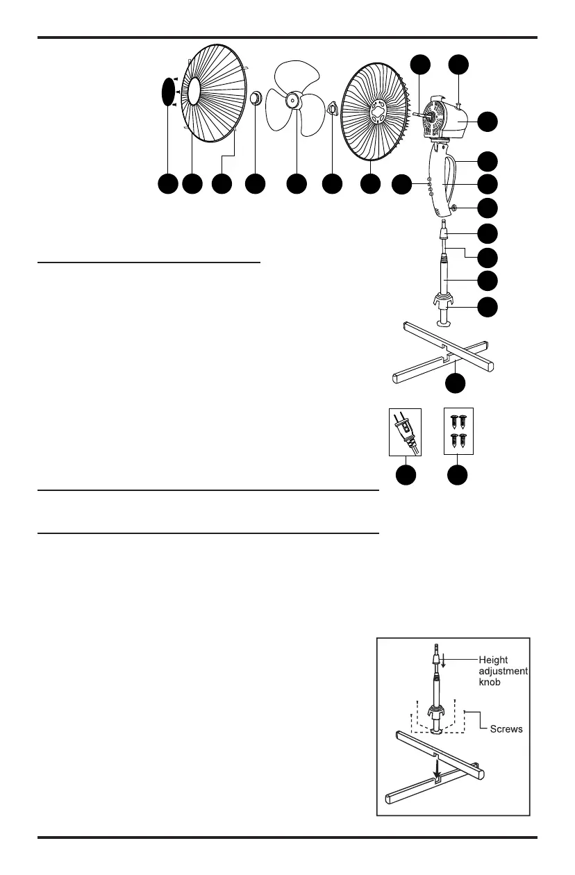
AB C D E
F
G
H
I
J
K
L
M
N
O
P
Q
R
S
T
U
A) Cubierta de la rejilla de
plástico con tornillos (3)
B) Rejilla frontal
C) Gancho de la rejilla
D) Tapa de la hélice
E) Hélice
F) Tuerca de seguridad de la
rejilla
G) Rejilla posterior
H) Panel de control
I) Eje del motor
J) Perilla de enganche de
oscilación
K) Cabezal del motor
L) Asa
M) Caja de control
N) Tornillo de seguridad
O) Perilla de ajuste de la
altura
P) Poste interior
Q) Poste exterior
R) Cubierta de la base
S) Patas de la base
T) Tornillos de la base (4)
U) Enchufe de seguridad con
fusible
DESCRIPCIÓN
DE LAS PARTES
Fig. 1
F
(
m b
P
t
F o
o
a
p
k
C
s
s
1
o
t
t
S
re
a
ARMADO
NOTA: Retire todo el contenido de la caja y asegúrese de
que todas las partes estén completas.
Paso 1: Ensamblaje de la base y postes (Fig.1)
1. Para ensamblar las barras transversales de la base (S),
haga coincidir las ranuras de ambas partes. Use los 4
tornillos de la base incluidos para asegurar la base del
poste exterior (Q) con las barras transversales de la base
(S). NOTA: El poste interior puede estar dentro del poste
exterior. Coloque el dedo en el agujero para retirar el
poste interior.
2. Gire la perilla de ajuste de la altura (O) en sentido
opuesto a las agujas del reloj para sacarla de los postes
exterior (Q) e interior (P). Inserte los polos interior (P) y
exterior (Q) a través de la cubierta de la base (R), y
deslícela (R) hacia la parte inferior del poste exterior (Q).
3. Inserte el poste interior (P) a través de la perilla de
ajuste de la altura (O) y extienda el poste interior (P)
hasta la altura deseada. Gire la perilla de ajuste de la
altura (O) en sentido de las agujas del reloj para asegu-
rar el poste interior.(O) dans le sens des aiguilles d'une
montre.
 Loading...