Français - 6
(Fig. 1)
1
Secure the
base of the outer pole (P) to the cross-bar
base (R) with the 4 base screws (S) provide
Place finger down the hole and pull out
i
the outer (P) an
cou Feed the inner (O) and
outer (P) pole through the base cap (Q), and
slide the base cap (Q) to the bottom of the
outer pole (P).
3
adjustment knob (N) an
pole (O) to the desired height. Secure the
inner pole by turning the height adjustment
kno
control box (Fig. 2)
1
control box, by turning it counter-clockwise,
(DO NOT REMOVE THE LOCK SCREW
COMPLETELY) the
and control box (J and L) on top of the inner
pole (O), the
secure it to the inner pole (O) by turning
it clockwise.
S
screw hole pointing downward) (F)
by aligning the guide holes with
the two rou
12 o'clock an
on the Motor Housing (J). Screw on
the grill lock nut (E) clockwise to
secure the rear grill (F) to
the motor housing (J).
2
the hole on the Fan Blad
matching the pron
Shaft (H) to the pron
the back of the Fan Blade
(
Secure the Fan Blad
Blad
it cou
3
rear grill (F) using the grill ho
at the bottom of the front grill.
T
with the grill clips (B) on the
outer ed
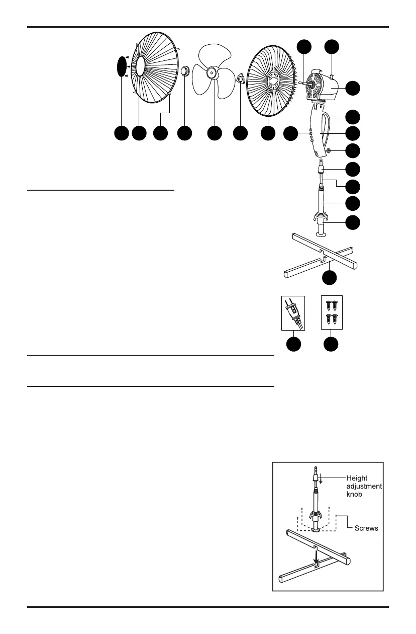
AB C D E
F
G
H
I
J
K
L
M
N
O
P
Q
R
S
T
U
A) Cache en plastique avec
vis (3)
B) Grille avant
C) Clip
D) Capuchon
E) Hélice
F) Écrou de blocage de grille
G) Grille arrière
H) Panneau de commande
I) Arbre moteur
J) Bouton d'enclenchement
de l'oscillation
K) Boîtier moteur
L) Poignée
M) Boîtier de commande
N) Vis de blocage
O) Bouton de réglage de la
hauteur
P) Montant intérieur
Q) Montant extérieur
R) Capuchon de socle
S) Pieds en croix
T) Vis des pieds (4)
U) Fiche de sécurité avec
fusible
DESCRIPTION
DES PIÈCES
Fig. 1
F
(
m b
P
t
F o
o
a
p
k
C
s
s
1
o
t
t
S
re
a
MONTAGE
REMARQUE: vider le contenu du carton et s'assurer que
rien ne manque.
Étape 1: Montage des pieds et des montants (Fig.1)
1. Assembler les pieds (S) en croix en les imbriquant
dans les encoches. Fixer le montant extérieur (Q) à la
croix (S) à l'aide des 4 vis de pieds (T) fournies. REMAR-
QUE: il se peut que le montant intérieur se trouve dans
le montant extérieur. Placer un doigt dans le trou et sor-
tir le montant intérieur.
2. Retirer le bouton de réglage de la hauteur (O) du
montant intérieur (Q) et du montant extérieur (P) en le
tournant à l'inverse des aiguilles d'une montre. Passer le
montant intérieur (P) et le montant extérieur (Q) dans le
capuchon de socle (R), et faire glisser le capuchon (R)
tout en bas du montant extérieur (Q).
3. Passer le montant intérieur (P) dans le bouton de
réglage de la hauteur (O) et étendre le montant
extérieur (P) de la hauteur souhaitée. Fixer le montant
intérieur en tournant le bouton de réglage de la hauteur
 Loading...