English - 2
ASSEMBLY
NOTE: Remove all contents from box and make sure that
all parts are present.
Step 1: Constructing the base and poles (Fig.1)
1. Connect the cross-bar base (S) together by matching
the slots in both pieces. Secure the base of the outer
pole (Q) to the cross-bar base (S) with the 4 base
screws (T) provided. NOTE: The inner pole may be inside
the outer pole. Place finger down the hole and pull out
inner pole.
2. Remove the height adjustment knob (O) from the
outer (Q) and inner (P) poles by turning it counterclock-
wise. Feed the inner (P) and outer (Q) pole through the
base cap (R), and slide the base cap (R) to the bottom
of the outer pole (Q).
3. Feed the inner pole (P) through the height adjust-
ment knob (O) and extend the inner pole (P) to the
desired height. Secure the inner pole by turning the
height adjustment knob (O) clockwise.
(Fig. 1)
1
Secure the
base of the outer pole (P) to the cross-bar
base (R) with the 4 base screws (S) provide
Place finger down the hole and pull out
i
the outer (P) an
cou Feed the inner (O) and
outer (P) pole through the base cap (Q), and
slide the base cap (Q) to the bottom of the
outer pole (P).
3
adjustment knob (N) an
pole (O) to the desired height. Secure the
inner pole by turning the height adjustment
kno
control box (Fig. 2)
1
control box, by turning it counter-clockwise,
(DO NOT REMOVE THE LOCK SCREW
COMPLETELY) the
and control box (J and L) on top of the inner
pole (O), the
secure it to the inner pole (O) by turning
it clockwise.
S
screw hole pointing downward) (F)
by aligning the guide holes with
the two rou
12 o'clock an
on the Motor Housing (J). Screw on
the grill lock nut (E) clockwise to
secure the rear grill (F) to
the motor housing (J).
2
the hole on the Fan Blad
matching the pron
Shaft (H) to the pron
the back of the Fan Blade
(
Secure the Fan Blad
Blad
it cou
3
rear grill (F) using the grill ho
at the bottom of the front grill.
T
with the grill clips (B) on the
outer ed
AB C D E
F
G
H
I
J
K
L
M
N
O
P
Q
R
S
T
U
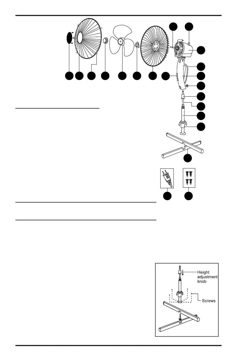
A) Plastic Grill Cover with
Screws (3)
B) Front Grill
C) Grill Clip
D) Blade Cap
E) Blade
F) Grill Lock Nut
G) Rear Grill
H) Control Panel
I) Motor Shaft
J) Oscillation Clutch Knob
K) Motor Head
L) Handle
M) Control Box
N) Lock Screw
O) Height Adjustment Knob
P) Inner Pole
Q) Outer Pole
R) Base Cap
S) Base Legs
T) Base Screws (4)
U) Safety Plug with Fuse
PARTS
DESCRIPTION
Fig. 1
F
(
m b
P
t
F o
o
a
p
k
C
s
s
1
o
t
t
S
re
a