EasyManua.ls Logo

IMT 5020 User Manual

Default Icon
118 pages
To Next Page IconTo Next Page
To Previous Page IconTo Previous Page
Page #7 background image
99903514: TELESCOPIC CRANE: 1-3 SECTION 1: OPERATION
For maximum safety during work near
powerlines, adhere to the following guidelines:
During windy conditions, allow additional
clearance.
Do not rely on cage-type boom guards, insulat-
ing links, or proximity warning devices for safety.
Adhere to the required distances listed in Figure
A-2.
Contact the utility company before beginning
work near powerlines.
Always assume overhead lines to be ener-
gized.
Avoid transporting a crane over uneven terrain.
When using rope to steady a load or restrain
spinning of the load, be aware that rope will also
conduct electricity, especially if wet or damp.
Reduce operating speed when in close proxim-
ity to powerlines in order to allow the operator
more reaction time.
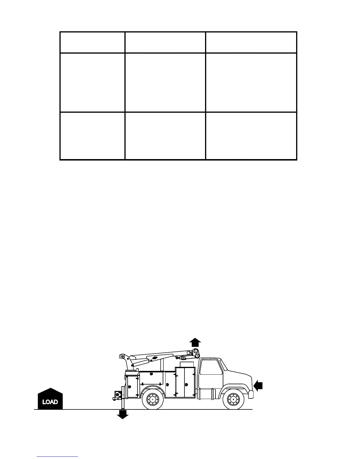
NORMAL VOLTAGE MINIMUM REQUIRED
kV (Phase to Phase) CLEARANCE Feet (meters)
OPERATION NEAR From 0 to 50 10 ( 3.05)
HIGH VOLTAGE From 50 to 200 15 ( 4.60)
POWERLINES From 200 to 350 20 ( 6.10)
From 350 to 500 25 ( 7.62)
From 500 to 750 35 (10.67)
From 750 to 1000 45 (13.72)
OPERATION IN From 0 to 0.75 4 ( 0.22)
TRANSIT WITH From 0.75 to 50 6 ( 0.83)
NO LOAD AND From 50 to 345 10 ( 3.05)
BOOM OR MAST From 345 to 750 16 ( 4.87)
LOWERED. From 750 to 1000 20 ( 8.10)
Figure A-2: Required Clearance of Cranes from Electrical Transmission Lines
IF ELECTRICAL CONTACT OCCURS:
1. Shut off all power.
2. Break contact of any person in contact with a
live conductor by using rubber hose, dry rope, or
dry wood. DO NOT attempt this unless you are
certain that all power is off.
3. Call 911 or the local emergency service.
4. Administer first aid.
5. Avoid the area around the crane, as high
voltage travelling through a crane will charge the
ground.
ELECTRICAL CONTACT FOLLOW-UP
1. Inspect and repair any equipment affected by
electrical contact.
2. Replace any wire rope which has had high
voltage contact.
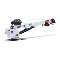
Figure A-3: Work Site Set-up
Outriggers fully out and down on
a firm and level surface.
Parking brake "ON."
Transmission in neutral.
No overhead obstructions.
No powerlines.
.
Load does not
exceed crane capacity.
20030115

Table of Contents

Other manuals for IMT 5020

Questions and Answers:

IMT 5020 Specifications

General IconGeneral
BrandIMT
Model5020
CategoryConstruction Equipment
LanguageEnglish

Summary

SECTION 0: INTRODUCTION

GENERAL

Manual provides knowledge for safe crane operation, not replacing regulations.

REVISIONS LIST

Details changes made to the manual over time by date and location.

SECTION 1: OPERATION

1-2: DAILY SAFETY INSPECTIONS

Daily checks for proper crane function and safety before operation.

1-7: CRANE CAPACITY AND LOAD LIMITS

Importance of capacity placards for safe lifting.

1-9: ANTI TWO BLOCKING SYSTEM

Prevents winch cable damage by stopping upward motion.

1-11: TASK PERFORMANCE

Step-by-step guide for operating the crane safely.

IMPORTANT! NOTES FOR SAFE OPERATION

Key safety precautions for crane operation.

SECTION 2: MAINTENANCE

2-2: MAINTENANCE SCHEDULE

Time intervals for performing various maintenance tasks.

2-5: HYDRAULIC SYSTEM

Maintenance and troubleshooting for the crane's hydraulic system.

2-6: WIRE ROPE & HOOK MAINTENANCE

Inspection, lubrication, and maintenance of wire rope and hooks.

2-8: PERIODIC CRANE INSPECTION

Regular inspections to ensure safe crane operation.

2-14: EXCESSIVE LOAD LIMIT SYSTEM (ELLS) TEST PROCEDURE

Steps to test the ELLS for proper function.

SECTION 3: REPAIR

3-2: REPAIR PRECAUTIONS

Safety measures before starting any crane repair work.

3-5: HYDRAULIC SYSTEM

Guidelines for maintaining cleanliness when working on hydraulics.

3-13: VALVEBANK

Description of valvebank components and troubleshooting.

SECTION 3A: CYLINDER REPAIR

3A-1. CYLINDER DISASSEMBLY

Step-by-step instructions for taking apart hydraulic cylinders.

3A-2. CYLINDER ASSEMBLY

Step-by-step instructions for reassembling hydraulic cylinders.

SECTION 4: INSTALLATION

4-2: CHASSIS PREPARATION

Steps to prepare the truck chassis for crane mounting.

4.5 MODEL SPECIFIC CRANE & HYDRAULIC INSTALLATION GUIDES

General guidance for model-specific installations.

SECTION 5: DECALS

5-2. “DANGER” DECAL DESCRIPTIONS

Explanation of hazard warning decals for operator safety.

SECTION 6: REFERENCE

INSPECTION CHECKLIST

A comprehensive list of items to inspect on the crane.

CRANE CAPACITY & STABILITY

Information on how crane capacity and stability are defined.

STABILITY TEST

Procedure for ensuring the crane's stability under load.

Related product manuals