99903514:TELESCOPIC CRANE: 4-7
SECTION 4: INSTALLATION
4.6 MODEL 1015 CRANE INSTALLA-
TION
CRANE INSTALLATION
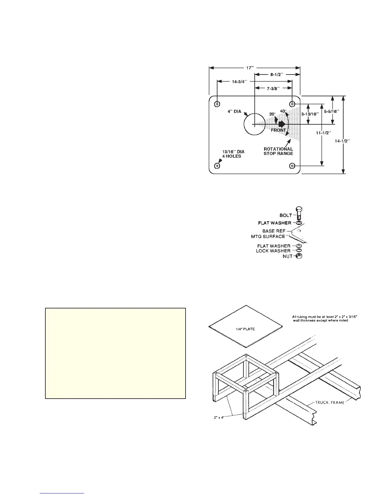
MOUNTING HOLE LAYOUT
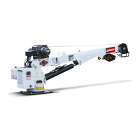
REINFORCEMENT
MINIMUM CHASSIS SPECIFICATIONS
BODY STYLE Conventional
Cab
WHEELBASE 137” - 161”
CAB TO AXLE 60” - 84”
FRAME SECTION MODULUS 5.91 in³
RBM 212,760 in-lb
(based on 36,000 psi yield frame mat’l)
FRONT AXLE RATING 4000 lb
REAR AXLE RATING 7500 lb
CRANE INSTALLATION
The crane requires a mounting space of at
least 14-1/2" wide by 17" long. If necessary,
the truck body can be reinforced to give
sufficient strength to support the crane in its
operating condition. Locate and drill the four
13/16" holes (see Mounting Hole Layout
drawing). Use a pilot drill first and then the 13/
16" drill. Cut the 4" diameter hole with a saw
after starting with a drill. Deburr all holes. Lift
the crane into position on the body. Use a
lifting device capable of supporting the crane -
650 lbs (295 kg).
Install the bolts, lockwashers, flat washers
and nuts to secure the crane to the chassis
(see Crane Installation drawing). Torque the
bolts to 200 ft. lbs. (27.66 kg-m).
NOTE
IN ADDITION TO THESE SPECIFICA-
TIONS, A HEAVY-DUTY BATTERY AND
ALTERNATOR ARE REQUIRED. IT IS
RECOMMENDED THAT THE VEHICLE
HAVE POWER STEERING AND DUAL
REAR WHEELS.
IMT RECOMMENDS ADHERENCE TO
THE UPPER LIMIT OF THESE SPECIFI-
CATIONS FOR BEST SYSTEM PER-
FORMANCE.
BODY REINFORCEMENT
If, after talking with the factory, it has been
determined that the body will not support the
crane with the full, rated load, the body can be
reinforced as shown. Use 1/4" fillet welds and
an AWS qualified welder.
20030115