2.2 Page 2.2 - 16 TS-LLD INSTALLATION GUIDE
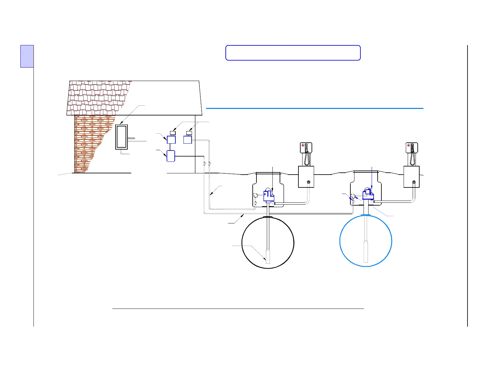
Figure 2.2-16 INCON TS-LLD Installation at FE PETRO STP or IST pumps
Single or Three Phase 240 VAC Applications
—
❖
—
Existin
Conduit
(Pump 1)
TS-LLD CUs
(Control Units):
# 2 and # 1
INCON TS-LLD Line Leak Detector
FE PETRO STP and IST (or STP-VS2 VFC)
Installation
Tank - Pump # 1
( "Standard" STP Single Phase
Installation )
An additional Single Phase 230 VAC
Relay Control Box (panel), and two additional
wires for the LSU, are required for
Three Phase pump Applications.
Motor Control Panels may be either:
Single Phase 230 VAC Relay Control Boxes,
- or - Single or Three Phase 230 VAC
Variable Frequency Controllers (VFCs).
NOTE:
1)
2)
Submer
ed
Turbine
Pump (STP)
Existing
Conduit
(Pump 2)
1
2
3 Phase
Starter
- or -
Variable
Frequency
Controller (VFC)
2
Motor
Control
Panels
Electrical
Power Panel
Epoxy
Filled
EYS
Seal
Fitting
Tank - Pump # 2
( FE PETRO Three Phase:
IST pump or STP Installation )
Explosion-
proof
Junction
Boxes
TS-LLD LSU (#2)
(Leak Sensing Unit)
at IST pump housing
Dispenser
# A
TS-LLD LSU (#1)
(Leak Sensing Unit)
at STP housing
Dispenser
# X
Reference Schematic Figures 2.3 - 11 & -12