Control Unit Installation Page 2.3 - 5 2.3
- - COM - -
N.O.
PUMP RELAY
F1
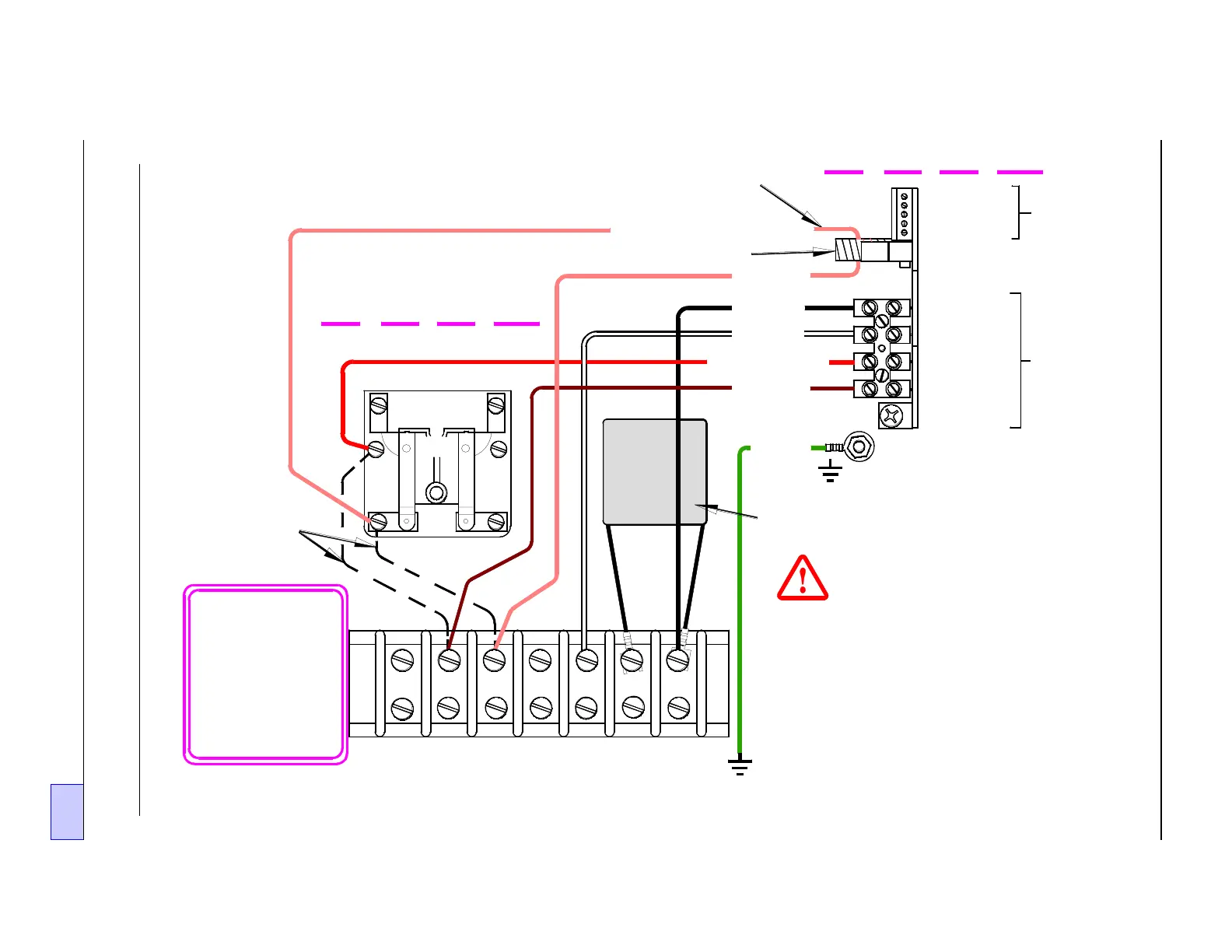
DANGER Electrical shock hazards!
Turn off and lock-out the submersible
pump power source (terminated at
L1 and L2), and the pump relay power
source (terminated at S2, from the
dispenser switch) BEFORE workin
on this equipment. Failure to turn off
these power sources will result in
severe injury or death.
L2 (BLK)
M2 (ORG)
N (WHT)
TS-LLD Control Unit
RLY COIL (RED)
S2 (BRN)
GROUND
(GRN)
- - - COIL - - -
Install the 1uF Line Filte r
Capacitor (INCON PN 020-0028)
Between L1 & L2
#8-32 Ground Stud
1 110V
2 NEU
3 P-OUT
TB2
1 485A
3 DSY1
2 485B
5 ALARM
4 DSY2
SIG RTN
4 P-IN
TB1
Pickup Coil
Pump Rela
Box
Remove wires
(shown as
dashed lines)
NO TE: O nly the
new wirin
that's required
within the
Pump Relay
Box, is shown
in this dia
ram.
S1 M2S2 M1 N L2L1
GROUND
STUD/SCREW
No termination - wire runs throu
h
the donut-shape d P ickup Co il
RLY N.O. CONTACT (ORG)
Figure 2.3-4 Typical Single Phase 240 VAC Pump Relay Box & Control Unit
Wiring Diagram