Control Unit Installation Page 2.3 - 7 2.3
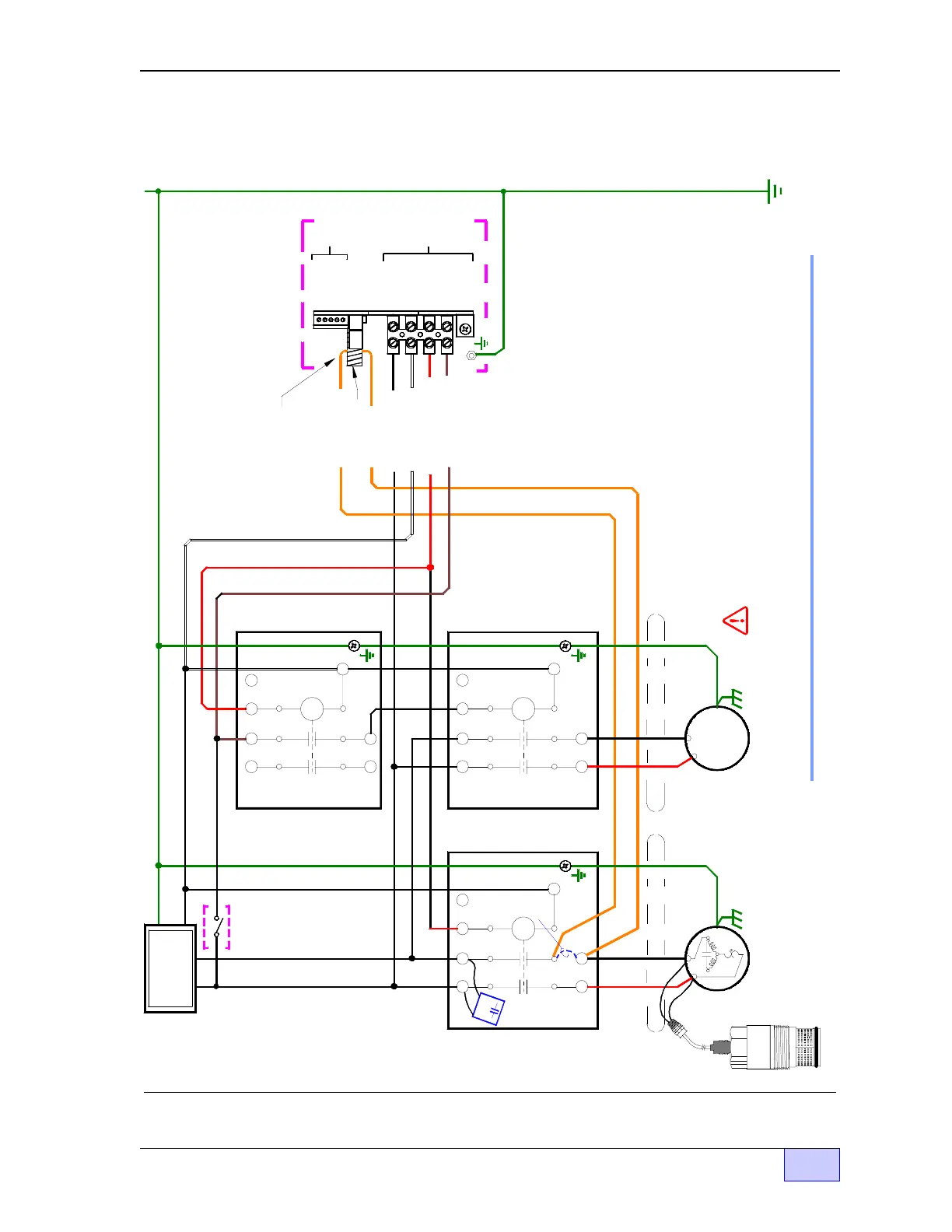
Figure 2.3-6 Single Phase 240 VAC Multiple Pump & Manifolded Line with Single LSU & CU
Interface Schematic
INCON TS-LLD - 1 LSU Multiple Pumps & Manifolded Lines - Wirin
Dia
ram
GND
GND
Pump Control
Relay Box # 1
(remove dashed wires)
P/N
020-0028
STP #1 Motor & LSU
TS-LLD LSU
at Leak Detection Port:
STP # 1 Pump Housing
OL
Install Line Filter
Cap at L1 and L2
N
M1 M2
Remove Wires
(dashed lines)
STP # 2 Motor
Conduit
to pump
Junction
Box
GND
M1
Pump Control
Relay Box # 2
M2
N
L1 L2 S1S2
Dispense
Switch(es)
Electrical
Power
Panel
L1 L2
N
GND
Aux. Relay Box
L1
M1
L2 S2 S1
M2
N
L1 L2 S2 S1
DANGER ELECTRICAL SHOCK HAZARDS. TURN OFF AND LOCK-OUT THE
SUBMERSIBLE PUMP POWER SOURCE AT THE CIRCUIT BREAKER - BEFORE -
WORKING ON THIS EQUIPMENT. FAILURE TO TURN OFF PUMP & DISPENSER
POWER SOURCE WILL RESULT IN SEVERE INJURY OR DEATH.
1) The Leak Sensing Unit (LSU) is installed at STP # 1
2) In line check valves are required at the output of
each RedJacket Submerged Turbine Pump
3) All ancillary pumps must be controlled / enabled
by the Aux. Relay Box as shown.
4) Only STP #1 Runs during line leak tests
NOTES
GND
No connection.
Wire is routed
through the
donut-shaped
Pickup Coil
Pickup Coil
TS-LLD Control Unit (CU)
Power Source = L1
Neutral (WHT)
RLY COIL (RED)
Dispense ( BRN)
Pump On Sig.
M1 (ORG)
L1 Line (BLK)
RLY N.O. (ORG)
1 485A
TB1
TB2
SIG RTN
4 P-IN
3 P-OUT
2 NEU
1 110V
5 ALARM
4 DSY2
F1
3 DSY1
2 485B