2.4 Page 2.4 - 4 TS-LLD INSTALLATION GUIDE
Programming the TS-2000
Alarm Relays
From ALARM RELAYS setup menu, select YES for LN LEAK RY1 to activate the
audible alarm inside of the console should a line leak occur. Select YES for LN
LEAK RY2 to control an external device that is wired to these contacts.
Alarm Reports
From SYSTEM setup menu, enable Report Alarms to have alarm reports printout
automatically at the console report printer. As with the TS-1000, Line Test
Reports and Line Test History Reports can be printed using the report key (see
previeous page for examples).
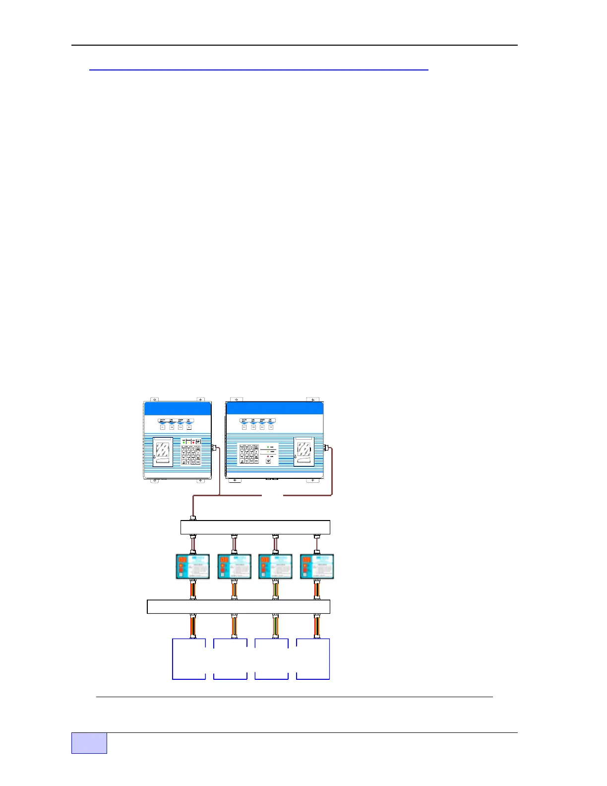
TS-1001 / TS-2001
LLDI
Interface
The Line Leak Detector Interface to these console uses a 4 conductor, 22 AWG,
communications grade cable for the RS-485 protocol. See Figures 2.4-4 and
2.4-5 for additional details.
See the TS-1001 / TS-2001 Setup
Programming Guide (P/N 000-1053)
for programming details and available
reports.
Many line-related reports can be
printed at the console by using the
report key. See the TS-1001 /
TS-2001 Sample Reports Document
(P/N 000-1394) for Line – Test,
Diagnostic, and History Reports.
Also, in the sample reports document,
see Line Alarm Reports for active line
alarms, cleared line alarms, or line
alarm history reports.
240 AC POWER WIRING Trou
h Only
Motor Control Panels
( Relay Boxes - or - Starters )
Communications Wirin
Trou
h Only
or
Figure 2.4-4 TS-1001 / TS-2001 LLDI Typical Connecting Hardware Layout