User’s Manual 14 Rev. 1.0
2019-04-29
TLE5501
TMR-Based Angle Sensor
Connection to a micro controller
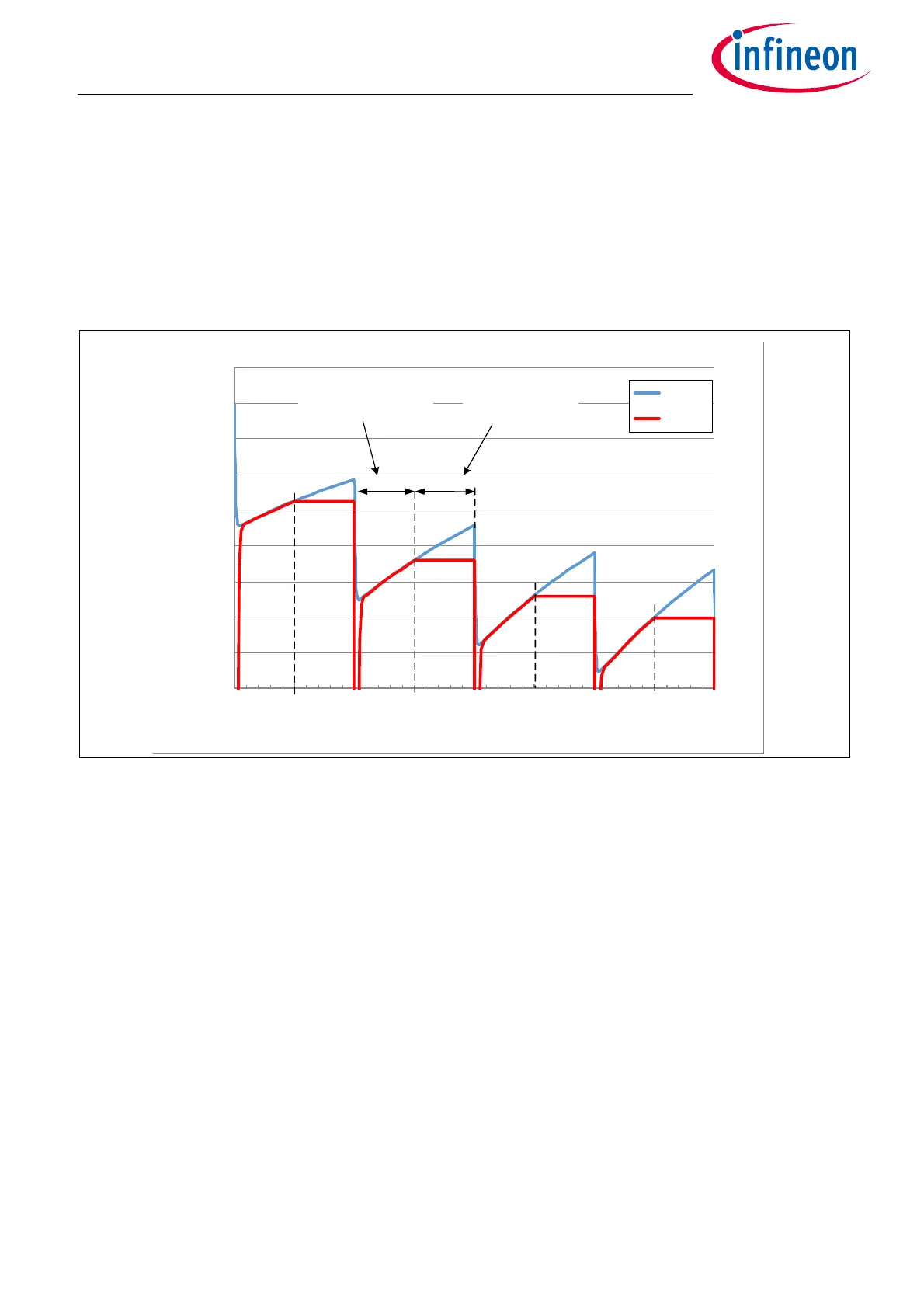
3.2.3 Oversampling
As seen in Chapter 3.2.1 the sampling frequency f
sample
is mainly given by the buffer capacitor C
b
. In some
cases, it might be necessary to perform an oversampling, i.e. to measure the same value several times and
calculate the average to increase resolution. Figure 13 shows an extreme condition with C
b
= 1nF, a sampling
time of 1µs and a hold time of 1µs, giving a total conversion time of 2µs. In this case the buffer capacitor C
b
is
not full charged as the time constant of the bridge is much larger than the sampling time. After each sampling
step, the voltage drops further and can not fully recover in the following hold time.
Figure 13 ADC voltage for a sampling time of 1µs and a conversion time of 1µs
As a consequence, the measured sine and cosine output voltage has an error which can contribute to an
additional angle error. As long as it is a constant and stable condition, this amplitude error is compensated
when doing the sensor calibration (matching of sine and cosine amplitude). Furthermore, as only the ratio of
sine and cosine amplitude is relevant for the angle calculation, a part of this error is canceled.
Nevertheless, the user has to verify in the specific application, whether the selected oversampling parameters
(sampling time and hold time), together with the external circuitry meets the requirements in angle accuracy.
2.460
2.465
2.470
2.475
2.480
2.485
2.490
2.495
2.500
2.505
0.0 1.0 2.0 3.0 4.0 5.0 6.0 7.0 8.0
U (V)
time (µs)
U @ Cb
U_ADC
hold time
S/H switch open
sampling time
S/H switch closed

 Loading...
