User’s Manual 15 Rev. 1.0
2019-04-29
TLE5501
TMR-Based Angle Sensor
Calibration
4 Calibration
Before the TLE5501 can be used in an application, a calibration on system level has to be performed. The four
analog output signals SIN_P, SIN_N, COS_P, COS_N have usually an offset and an amplitude mismatch. This
has to be corrected before the angle can be calculated. Also, SIN and COS output signals have an orthogonality
error, means that they are not precisely 90° phase shifted. This needs also to be compensated to achieve the
accuracy specified in the datasheet. The calibration has to be done for all single ended signals which are
intended to be used. In case the differential signals are used, there must also be a compensation based on the
differential signals. Further details how to perform the calibration is described in the Application Note
“TLE5xxx(D)_Calibration_360”. Usually this calibration is performed at 25°C and at 0h.
The sensor TLE5501 is intended to be used with a specified magnetic field strength, which range is specified
in the datasheet. It has to be ensured that the device is not exposed to a magnetic field outside the specified
range over the whole temperature and lifetime range. Also the temperature characteristics of the magnet in
use has to be considered. For the usual magnet material, the magnetic field strength is reduced with
increasing temperature and increased with decreasing temperature. Therefore, depending on the maximum
and minimum temperatures in the application, the magnetic field at 25°C and 0h has to be adjusted
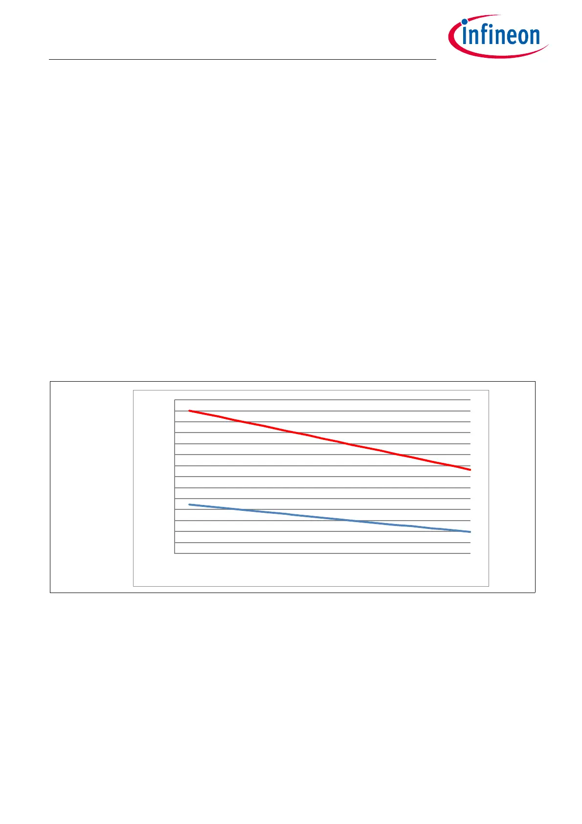
accordingly in order not to violate the specified limits. Given a specified range of 25mT to 80mT for the allowed
magnetic field range and considering a ferrite magnet material with Tc = -2000ppm/K, the magnetic field in the
whole temperature range will be as shown as in Figure 14.
Figure 14 Magnetic field for a ferrite magnet with TC = -2000ppm/K in the full temperature range.
Specified minimum and maximum field values of 25mT and 80mT are considered.
Different magnet material leads to a different temperature characteristic of the magnetic field. This has to be
taken into account by the user of the device.
To achieve the specified angle accuracy of TLE5501, it has to be ensured that the magnetic field during lifetime
and temperature range of the application does not deviate too much from the initial calibration condition at
25°C/B
0
/0h. B
0
is the magnetic field at initial calibration condition at 25°C/0h.
This condition is met when the deviation of B
0
over lifetime (due to e.g. aging of magnet and mechanical airgap
variations) is less than 10%.
15
20
25
30
35
40
45
50
55
60
65
70
75
80
85
-50-250 255075100125150
B (mT)
T (°C)

 Loading...
