EasyManua.ls Logo

Infineon XENSIV TLI4971 User Manual

Infineon XENSIV TLI4971
31 pages
To Next Page IconTo Next Page
Page #1 background imageLoading...
Page #1 background image
Application Note Please read the Important Notice and Warnings at the end of this document Rev. 1.30
www.infineon.com page 1 of 31 2022-03-01
AppNote_TLI4971_ProgGuide
Current Sensor TLI4971
Programming Guide and User Manual
About this document
This document describes how to program the TLI4971 with the Infineon proprietary one wire interface (SICI).
Timing of the serial inspection interface.
Command structure and commands for write/read and EEPROM access.
A description of the user changeable EEPROM section.
Details on the diagnosis mode.
For productive in circuit programming Infineon recommends to use a verified programmer which has been a
coproduction development between Infineon and CGS. For further documentation please refer to Sensor
Programmer CGS Computer Gesteuerte Systeme GmbH (cgs-gruppe.de)
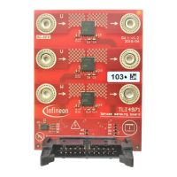
Further Infineon provides a programming board for laboratory usage.
Scope and purpose
TLI4971 Coreless Current Sensor Feature set, EEPROM and interface description.
Intended audience
Users who use the high variety of the TLI4971 current sensor by programming the functionality like full scale
or over current detection, operating modes etc. to their need.
Current Sensor Module Developers.
Question and Answer IconNeed help?

Do you have a question about the Infineon XENSIV TLI4971 and is the answer not in the manual?

Infineon XENSIV TLI4971 Specifications

General IconGeneral
Product CategoryCurrent Sensors
Sensing TechnologyHall Effect
Output TypeAnalog
PackageSOIC-8
Operating Temperature-40 °C to +125 °C
Output InterfaceAnalog Output
Accuracy (typical)0.5 %
Measurement Range±25A to ±120A
Supply Voltage3.3 V to 5.5 V

Summary

Application and Programming Circuit

Circuit / Precondition

Describes prerequisites for using the SICI interface and programming.

In-circuit programming

Details on programming the EEPROM via the digital interface.

Serial Inspection and Configuration Interface (SICI)

Hardware Implementation

Shows the hardware setup for SICI communication.

Entering Communication Mode

Explains how to activate the SICI interface.

Communication timing

Details the timing specifications for SICI communication.

Interface Timing Definition

Defines parameters for SICI interface timing.

Definition of Voltage Levels

Specifies voltage levels for SICI communication.

Interface Description

Command Structure

Describes the format of SICI commands.

Read / Write Command

Explains how to read and write data using SICI.

Interface Commands

Lists available commands for the SICI interface.

Write and programming sequence

Details the sequence for writing to EEPROM.

Temporary register

Explains the use of temporary registers for testing.

Read Example (temperature register read out)

Provides an example of reading temperature data.

EEPROM

EEPROM Content

Details the organization and content of the EEPROM.

Programming Example

Guides through a complete EEPROM programming sequence.

Margin Test

Explains how to test EEPROM cell threshold voltages.

Cyclic Redundancy Check

Describes the CRC calculation for EEPROM data integrity.

Code example CRC calculation

Provides a code example for CRC calculation.

Operation Mode

Single-Ended Mode

Describes the single-ended operational mode.

Fully-differential Mode

Explains the fully-differential operational mode.

Semi-differential Mode

Details the semi-differential operational mode.

How to connect the sensor in a 5V domain

Single-Ended Mode

Shows connecting the sensor in single-ended mode to a 5V MCU.

Semi and or Fully-differential Mode

Shows connecting in differential modes to a 5V MCU.

Diagnosis Mode

Glossary

Related product manuals