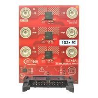
Figure 18 TLI4971 (fully-differential mode) connected to differential ADC
5.3 Semi-differential Mode
In Semi-Differential Output Mode, the sensor is using a chip-internal reference voltage. This reference voltage is
then provided on the VREF. Therefore, the reference voltage can be monitored by the microcontroller and/or
used for other devices as a reference voltage (cascade setup). The current-dependent output signal is provided
as single-ended signal on AOUT.
The Quiescent Voltage will be set to a value in the middle of the voltage range or at 1.5V (V
OQbid
) to measure
bidirectional current values, whereas when the direction of the current is already known by the application, the
quiescent voltage can be set to a lower value (V
OQuni
) in order to better exploit the full voltage range.

 Loading...