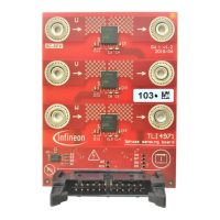
1 Application and Programming circuit
The sensor has implemented a serial interface to set the EEPROM content. This chapter describes the hardware
environment to program the device. Further, it shows the recommended circuit for a three-phase GPD
application.
Figure 1 TLI4971 3-phase GPD application circuit for semi and or fully- differential mode
The protection functionality is covered by two open drain outputs (OCD1 and OCD2) to indicate an overload
and to protect the system in case of an over current event. The OCD1 output shut down the HV gate-driver. The
OCD2 connect to an interrupt input of the microcontroller.
1.1 Circuit / Precondition
Each device can be set separately via the SICI-one wire interface.
In order to communicate with the sensor via the SICI one wire interface the A
OUT
lines of each sensor need to
connect to a microcontroller.
As a first step of the programming procedure, the parameter set has to download into the volatile memory area
of the sensor via the SICI interface.
In a second step, the parameter needs to get stored into the EEPROM by sending the programming command
and applying the programming voltage on OCD2 pin.
OCD2 and V
DD
need to be controlled by the programmer.

 Loading...