User’s Manual 3 Rev. 1.0
2019-04-29
TLE5501
TMR-Based Angle Sensor
Application Circuits
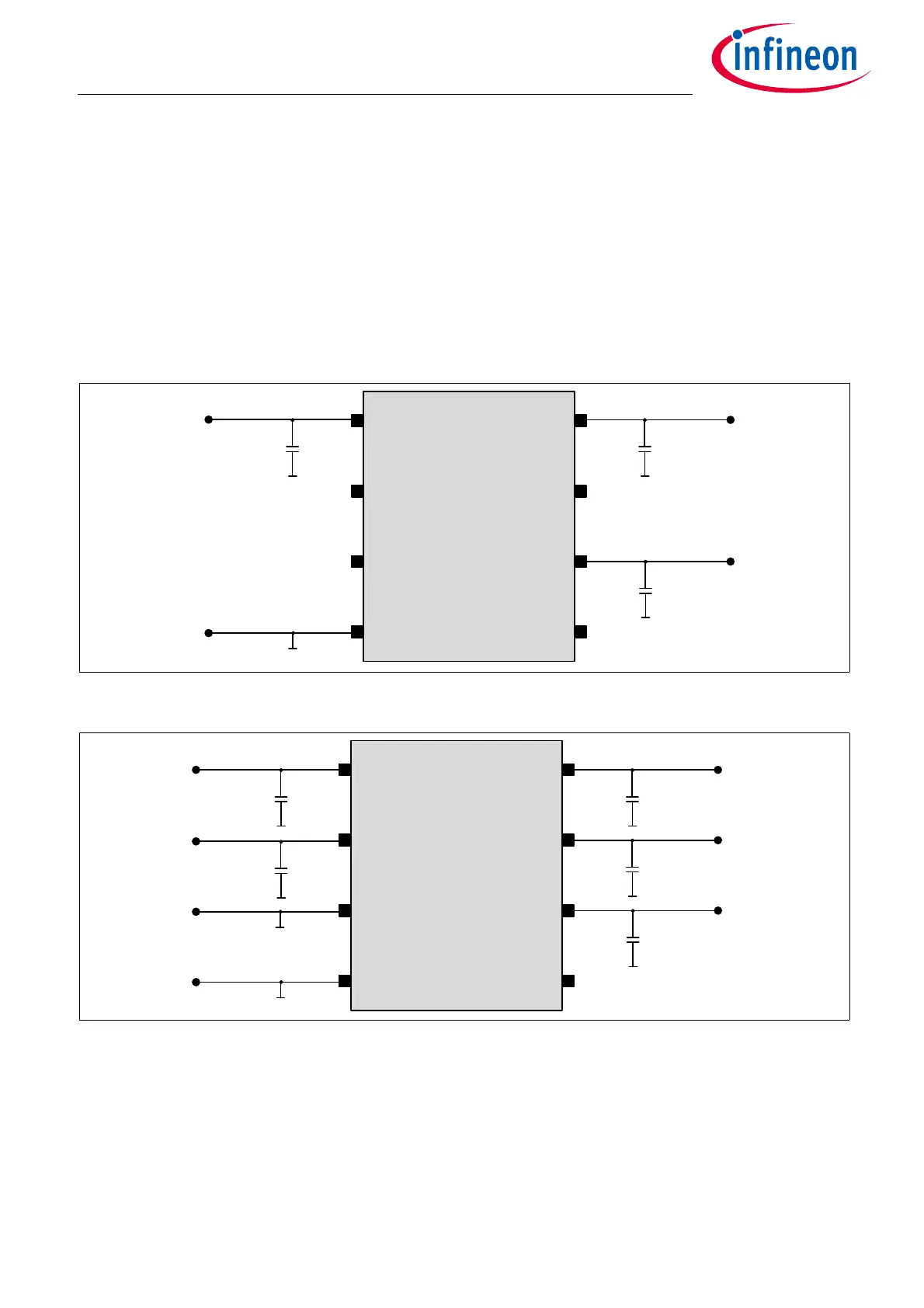
1 Application Circuits
The application circuits in this chapter show the various connection possibilities of the TLE5501. It can be used
in a single ended mode (only one sine and one cosine signal, Figure 1 and Figure 3) and in a differential mode
with a total of four output signals (Figure 2 and Figure 4).
To fully implement the safety concept of the TLE5001 E0002 version and achieve highest diagnostic coverage,
the four output signals have to be sampled singled ended. This is necessary, as the proposed external safety
mechanisms in the Safety Manual act on the single ended signals. Nevertheless, to reach highest angle
accuracy, the differential calculated angle shall be used for the application. The single ended signals are for
diagnostic only.
Figure 1 Application circuit for TLE5501 E0001 single ended signal used
Figure 2 Application circuit for TLE5501 E0001 differential signal used
VDD
GND1
SIN_P
100n
SIN_P
VDD
COS_P
GND1
COS_N SIN_N
GND2
TLE5501
C
b
C
b
COS_P
COS_N
VDD
GND1
SIN_P
SIN_N
100n
GND2
SIN_P
VDD
COS_P
GND1
COS_N SIN_N
GND2
TLE5501
C
b
C
b
C
b
C
b

 Loading...
