User’s Manual 11 Rev. 1.0
2019-04-29
TLE5501
TMR-Based Angle Sensor
Connection to a micro controller
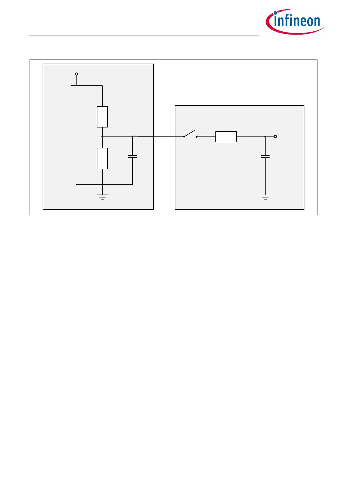
Figure 10 Equivalent circuit of TMR bridge (only half bridge is shown) and SAR ADC input
3.2.1 Load step
The following consideration is made with the initial condition that the buffer capacitor C
b
is fully charged, the
S/H switch is open and the sample and hold capacitor C
SH
is decharged. In this condition, the voltage at C
b
is
V
DD
/2 and the voltage U
ADC
= 0V.
When the S/H switch is closed, charge is flowing from C
b
to C
SH
, the voltage at C
b
drops and the voltage at C
SH
,
U
ADC
, increases. In addition, charge is flowing from the supply voltage V
DD
via the TMR resistor R
TMR
to charge
C
b
.
The following parameters are assumed: V
DD
= 5V, R
TMR
= 8kΩ, C
b
= 1nF, R
SH
=2kΩ, and C
SH
= 7pF.
The time constant τ
br
for charging C
b
via R
TMR
is given by τ
br
= R
TMR
/2 x C
b
= 4µs (see also Chapter 2.2).
For charging C
SH
the time constant τ
SH
= R
SH
x C
SH
= 14ns. Therefore, the charging of C
SH
and also the de-
charging of C
b
is much faster (~ 9x14ns = 140ns) than the recovery of the voltage at C
b
(~ 9x4µs = 36µs).
Due to this, with the assumption that τ
br
>> τ
SH
the voltage at C
b
drops by a value of ΔU which can be
approximated as follows (Equation (3.1)):
(3.1)
With above parameters and U
0
= 2.5V, the load step is calculated to ΔU = 17.4mV. The time constant τ
br
of the
bridge defines how long it takes until the voltage U
ADC
is settled with sufficient accuracy (error less than
0.5LSB). Therefore, the sampling time (time for which S/H switch has to be closed) must be larger than
9 x τ
br
= 9x4µs = 36µs.
Figure 11 shows this behavior. At t = 1µs the S/H switch is closed and remains so until t = 37µs. In the first
moment, the voltage drops by ΔU = 17mV and then increases with the time constant of the bridge τ
br
= 4µs.
GND
U
ADC
C
SH
R
SH
S/H
R
TMR
GND
VDD
C
b
R
TMR
TMR bridge
ADC
ΔUU
0
C
S
H
C
b
C
SH
+()
------------------------------
=

 Loading...
