User’s Manual 12 Rev. 1.0
2019-04-29
TLE5501
TMR-Based Angle Sensor
Connection to a micro controller
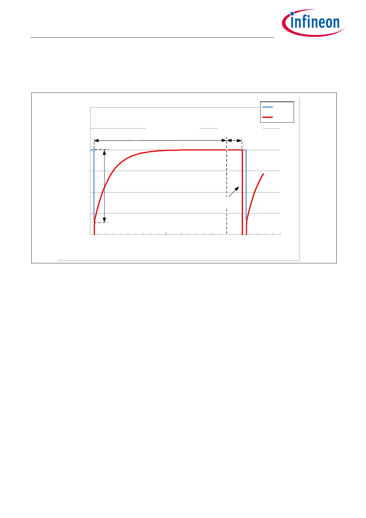
After 36µs the capacitors C
SH
and C
b
are almost fully charged, the S/H switch is opened and the ADC can start
with the conversion and will sample the correct voltage of V
DD
/2. After the hold time the capacitor C
SH
is
discharged and the next sampling phase starts.
Figure 11 Sampling and conversion of the TMR bridge signal with a SAR ADC.
The time constant of the bridge τ
br
= R
TMR
/2 x C
b
is determining the maximum possible sampling frequency
f
sample
. In above example the maximum sampling frequency is estimated to f
sample
~ 27.7kHz (Equation (3.2))
In reality, the achievable sampling frequency is lower, as also some additional time has to be included for the
hold time of the ADC. Sampling time and hold time are depending on the settings of the microcontroller in use.
(3.2)
The relation between buffer capacitor C
b
, sampling frequency f
sample
and sensor bandwidth f
rotation
is shown in
Figure 12. In this calculation, sensor bandwidth f
rotation
is calculated assuming that the phase shift Φ between
external magnetic field and electrical sine/cosine output signal is less than 0.2° according to Equation (2.5).
R
TMR
is assumed to be 8kΩ.
2.480
2.485
2.490
2.495
2.500
2.505
2.510
0.0 10.0 20.0 30.0 40.0 50.0
U (V)
time (µs)
U @ Cb
U_ADC
C
SH
discharged
Load step ΔU
hold time
S/H switch open
sampling time
S/H switch closed
f
sample
1
9 τ
br
⋅
---------------
<

 Loading...
