User’s Manual 7 Rev. 1.0
2019-04-29
TLE5501
TMR-Based Angle Sensor
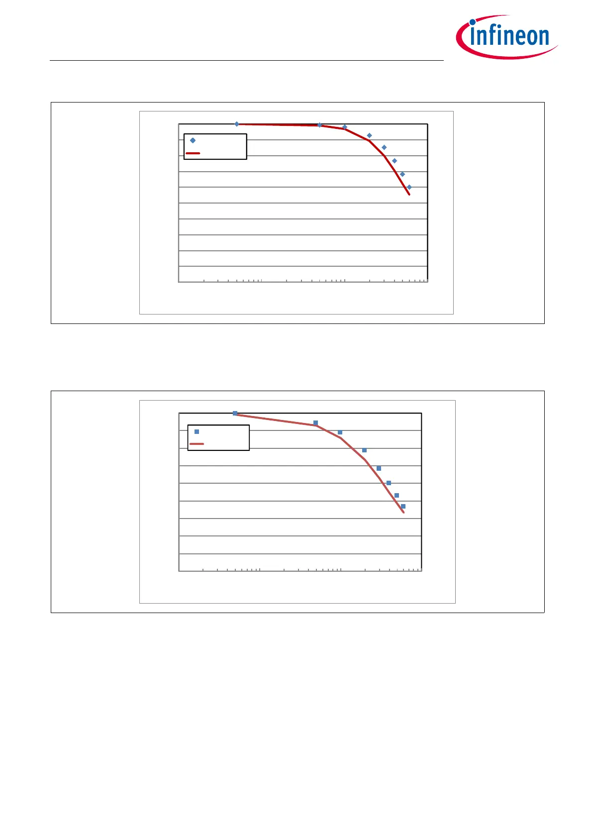
Transient behavior
Figure 7 Normalized output amplitude for an AC magnetic field excitation. Bridge resistor R
TMR
=
8kΩ, C
b
=1nF. For the analytical calculation, the values R = 4kΩ and C
b
= 1nF are used
(Equation (2.2))
Figure 8 Phase shift between output signal and excitation for an AC magnetic field. Bridge resistor
R
TMR
= 8kΩ, C
b
=1nF. For the analytical calculation, the values R = 4kΩ and C
b
= 1nF are used
(Equation (2.3))
The transient behavior of the TMR output can be approximated with a simple RC model, using R = R
TMR
/2.
0.00
0.10
0.20
0.30
0.40
0.50
0.60
0.70
0.80
0.90
1.00
100 1000 10000 100000
U(t)/U0
frequency (Hz)
Ampl. pSPICE
Ampl. analyt.
-90
-80
-70
-60
-50
-40
-30
-20
-10
0
100 1000 10000 100000
Phase (°)
frequency (Hz)
Phase pSPICE
Phase analyt.

 Loading...
