User Manual 3-4 V2.1
TriBoard TC3X9 TH V2.0(1) and TriBoard TC3X9 V2.0 2017-11
TriBoard Manual TC3X9
Hardware: TriBoard TC3X9 TH V2.0(1) and TriBoard TC3X9 V2.0
TriBoard Information
3.7.1 Serial Connection to PC
After the first connection of USB to a PC the needed driver will be installed automatically. During this there will
be created a new COM port on PC. This COM port can be used to communicate with the board via ASCLIN0 of the
device. Per default the ASCLIN0 is used on P14.0 and P14.1 (e.g. Generic Bootstrap Loader) . In case you will use
the Generic Bootstrap Loader via CAN or ASCLIN0 via P15.2 and P15.3 you must:
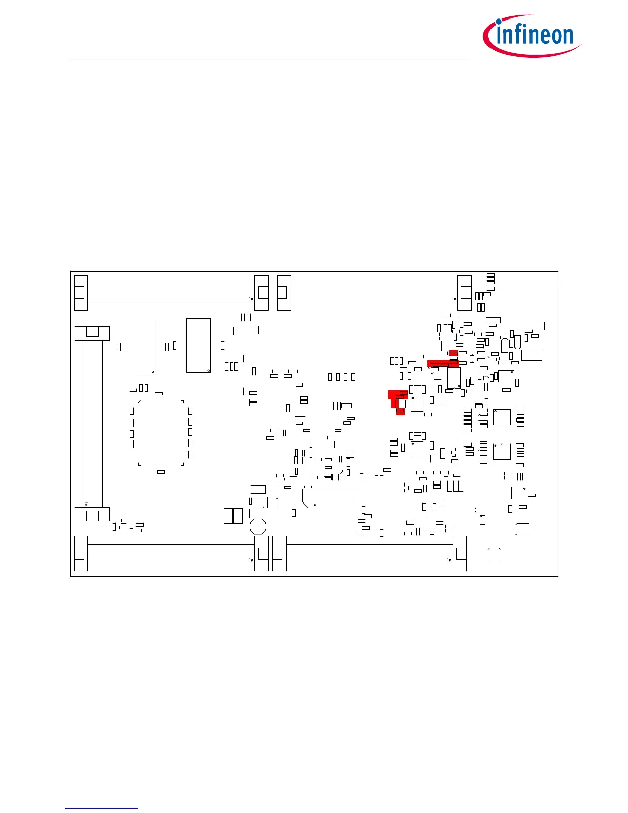
– remove R436 and R437 (this disconnect the serial connection from P14.0 and P14.1)
– remove R301 and R302 (this disconnect the CAN0 transceiver from P20.7 and P20.8)
– assemble R438 and R440 with 0R resistor (size 0603) to connect P15.2 and P15.3 to serial connection
– assemble R303 and R304 with 0R resistor (size 0603) to connect P14.0 and P14.1 to CAN0 transceiver
The mentioned resistors are red marked in Figure 3-2.
Figure 3-2 Resistors for ASC connection (ASC0)
3.7.2 miniWiggler JDS
The miniWiggler JDS is a low cost debug tool which allows you access to the JTAG of the device. Make sure that
you have the latest DAS release. Debugging is possible via the DAS Server ‘UDAS‘. Please contact your prefered
debug vendor for support of DAS.
If you have connected the board to the PC and there runs the DAS server, then a working connection is visible via
the green ACTIV LED.
The status RUN LED is switched on/off through the DAS Server, depending on the used debugger (client).
IMPORTANT: Make sure that there is no or a tristated connection on X401 (OCDS1) and X402 (DAP) if the ACTIV LED
is on.

 Loading...

