This document is a user's manual for the Infineon Programmer Kit for the TLI4970 Current Sensor, specifically software description for evaluation kits, Rev. 1.2, dated 2013-06-06.
Function Description
The Programmer Kit is designed to visualize data from TLI4970 current sensors. It enables users to read and write the sensor's EEPROM and to read and write various internal registers of the connected TLI4970. The kit provides a graphical user interface (GUI) to monitor the sensor's data output, which can then be saved in a CSV file for analysis using external software like Excel or Matlab. The GUI also allows configuration of internal sensor settings, either temporarily in RAM or permanently in the EEPROM.
The Programmer Kit typically includes:
- A CD-ROM with the PC software.
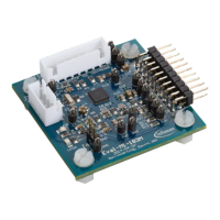
- A PGSISI-2 programmer.
- An external power supply.
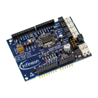
- An Evaluation Board.
The PC software communicates with the sensor via the PGSISI-2 programming interface. The PGSISI-2 periodically requests the current value from the sensor and relays the response to the PC for interpretation and visualization.
Important Technical Specifications
Hardware Requirements:
- x86 processor at 900 MHz or higher.
- 30 MByte RAM.
- 5 MByte hard disk space for installation files (more needed for saving sensor data).
Software Requirements:
- Microsoft Windows 2000 or higher.
- Microsoft .NET Framework 2.0 or later (included with setup.exe, typically pre-installed on Windows 7).
Communication Rate:
- Maximum communication rate between PC and sensor is approximately 41,700 samples per second.
Evaluation Board Specifications (Absolute Maximum Ratings):
- Supply voltage on "External supply" pins (VDD): -0.3 V to +5.5 V.
- Maximum primary current in socket (IP_Socket): -10 A to +10 A (sensor mounted inside socket).
- Maximum primary current for soldered device (IP_PCB): -50 A to +50 A (sensor soldered to PCB, no sensor in socket).
- Maximum isolation voltage (UISO): 50 V (voltage between current rail and measurement GND).
- Maximum ambient temperature (TA_Max): +60 °C.
- General conditions (unless specified): VDD = 5.0 V; TA = 25 °C.
Sensor Output:
- One sample is a 16-bit output word, containing a current value, an overcurrent detection flag, and a parity bit for communication error detection.
File Size for Data Logging:
- The file size for recorded data depends on the sample rate. The maximum growth rate is around 2 MByte per second, potentially leading to files of 1 GByte or more after several minutes.
Usage Features
Installation:
- Run "setup.exe" from the installation folder.
- Follow the typical Microsoft Windows installer steps, accepting the license agreement and selecting the installation folder.
- The installer will install the programmer driver (PGSISI-2) and the GUI software.
- Once installation is complete, the GUI can be launched from the Windows start menu: Start -> All Programs -> TLI4970 -> TLI4970 Evalkit Software.
Connecting to the Programmer:
- The main window displays a list of connected PGSISI-2 programmers (identified by serial number).
- Select a programmer from the list and click "Connect."
- After connecting, select the correct sensor type (e.g., TLI4970) from the "Sensor" field.
Normal Operation:
- All necessary voltages for the sensor and level shifter ICs are supplied by the PGSISI-2.
- Jumpers should be in their default settings (e.g., J4 Vprog Closed, J8 CS_B Closed, J10 DIN_OCD Open, JP4 GND-PGSISI, JP6 V3V3-PGSISI).
- Current to be measured can be applied via 4mm "Banana" plugs or 7mm screw bolts.
- The SPI interface can be monitored via connectors JP1, allowing connection of a logic analyzer.
- The overcurrent response and SICI interface (for EEPROM programming) can be monitored via the OCD-pin.
Operating with External Power Supply:
- External VDD can be applied to the sensor via "External supply" pins (JP3).
- Jumpers JP4 and JP6 must be set to "Extern" to use an external supply.
- The PGSISI-2 still supplies the level-shifters.
- Note: When using an external supply, the "RESET" and "POWER" buttons on the GUI only operate on the GUI, not the sensor. A "Sensor Reset" or EEPROM reload requires recycling the external supply voltage.
Graphical User Interface (GUI):
- Main Window: Displays connected programmers, allows sensor selection, and provides access to sensor data and settings.
- Data Visualization: Current values are displayed in a graph and a text box.
- Sample Rate: Configurable, with a default of 100 Samples per second to prevent PC lag with low processing power.
- Graph View:
- Dimensions can be configured by right-clicking the graph area.
- "Autoscale" automatically adjusts y-axis min/max values.
- Y- and x-axes can be adjusted manually.
- Small values may not be accurately displayed due to graph resolution.
- "Overcurrent" field changes to "True" if detected by the sensor.
- Status Information: Displayed as a list in the "List of Status Information" field.
- Tabbed Window: Contains "Sensor Parameters" and "Data View" tabs.
- Sensor Parameters Tab: Allows changing predefined sensor parameters (e.g., Bandwidth, OCD Level, Glitch Filter, DOUT Driver Strength) either in RAM or EEPROM. Changes are only possible when measurement is stopped.
- Data View Tab: Shows the last 1000 samples, including Index, Current [A], Parity OK, OCD active, and raw SPI data.
- Index: Sample index, used to detect lost samples (increments "PGSISI 2 Error count").
- Current: Current in ampere.
- Parity OK: Indicates if sample parity is "OK" or "wrong."
- OCD active: Indicates overcurrent detection (evaluates bit 13 of SPI frame).
- SPI data: Raw SPI data received from the sensor.
- All samples during a measurement are stored in a CSV file (default location: "C:\ProgramData\Infineon Technologies\TLI4970").
- "Save" button allows storing monitored samples to a user-defined text file.
EEPROM Window:
- Used to read and write the TLI4970 EEPROM.
- Displays 16-bit lines, with EEPROM addresses and field names on the left.
- Selecting a field highlights the corresponding bit field in the center and shows its value in hexadecimal and decimal on the right.
- Values can be changed in hex or decimal.
- Buttons:
- Burn EEPROM: Writes displayed values to EEPROM. Involves power cycling, enabling test mode, writing, and then comparing EEPROM content with displayed values. An error message appears if content differs.
- Read EEPROM: Reads EEPROM values from the sensor, updates the table, and displays them. Involves power cycling and enabling test mode.
- Load: Loads an EEPROM setting from an XML file.
- Store: Saves current EEPROM register values to an XML file.
- Close: Closes the EEPROM window.
- Set in RAM: Sets displayed content only in RAM. EEPROM cells are not modified, and values will be overridden by EEPROM values after a sensor reset.
Maintenance Features
Power Management:
- The "Power is On" button turns the sensor's power on/off. It is recommended to turn off the power before unplugging the sensor or Evaluation Board.
EEPROM Protection:
- The jumper J4 can be opened to protect the sensor from false EEPROM programming during evaluation. In this state, only temporary RAM settings can be tested, and original settings are restored after a power cycle.
Error Handling:
- If the OCD pin is enabled and current exceeds the OCD level, EEPROM burning is interrupted because communication for the burn process and OCD output share the same pin, potentially leading to corrupted EEPROM.
- The "PGSISI 2 Error count" in the Data View increments if a sample is lost during communication (e.g., due to buffer overflow).
Software Information:
- The "Help" menu bar provides access to information about the current version of the Programmer Kit Software modules.
- The "About" window (Help -> About) displays versions of used libraries, including Evalkit, Firmware, Sensor Library, Class Library, FTDI Device Module, and Programmer Module.